Hardware-in-the-Loop Test Drives Development
Every product development effort begins with a plan—traditionally, in the form of diagrams such as Leonardo da Vinci’s ornithopter flying-machine drawings, but today, in the form of software representations. A successful effort will evolve from plan to working prototype—in the case of Leonardo’s aviation drawings, the process took about four centuries, whereas today, successful product development cycles are measured in months.
Nevertheless, it’s a mistake to try to jumpstart a development effort by moving from a paper or computer representation to hardware prototype too quickly. According to Guido Sandmann, automotive industry manager for the European region at MathWorks, “When you talk to automotive engineers, what they like to do, because it’s a lot of fun, is get into [the prototype vehicle] as fast as possible and begin testing.” However, at MathWorks, he said, “Our goal actually is to keep them at their desks as long as possible “—working in a model-based design and simulation environment performing testing, verification, and validation at the model level.
Leonardo might well have understood this concept. His models for the ornithopter were birds, and he wrote, “A bird is an instrument working according to mathematical law. It lies within the power of man to make this instrument with all its motions.”
Unfortunately, Leonardo left his desk in pursuit of working prototypes a few centuries too early. He lacked the internal combustion engine or lightweight materials that would have let him achieve the necessary power-to-weight ratio to get off the ground. He was unable to implement his bird models at the human scale.
Sandmann elaborated on the model-based environment in this month’s Automotive Test Special Report. But at the optimum time for transitioning out of that environment, he said, MathWorks offers its xPC Target tool, which enables you to execute Simulink and Stateflow models on a target computer for hardware-in-the-loop (HIL) simulation, rapid prototyping, and other real-time testing applications.
In addition, MathWorks offers the Vehicle Network Toolbox that, for example, enables engineers to acquire data from a CAN bus into a Matlab environment for analysis or connect a Simulink model to a CAN bus.
Noah Reding, product manager for automotive and aerospace at National Instruments, said his company provides a full understanding of the electronics in an application. “Whether you have passenger vehicles or big trucks or agricultural machines,” he said, “the electronics complexity is just growing.” NI strives to help engineers throughout their development cycles, including prototyping and HIL test.
The Product Development V Model
Citing the V model of product development, with the left leg of the V representing project definition and design while the other represents test and integration, Reding said, “We are focusing on a lot of those areas throughout the development process. We feel our platform is uniquely positioned to help engineers take care of all of those steps. There is a lot of value in being able to reuse the different components in the different stages.”
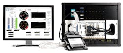
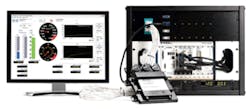
Relevant NI products, he said, include NI LabVIEW and CompactRIO for prototyping. In addition, he said, NI VeriStand (Figure 1) finds extensive use in automotive applications because it enables users to run simulation models and connect real-world I/O. In addition, he said, “The flexibility of our hardware platform gives engineers the ability to connect their models to whatever hardware they need to—whether that’s a CAN bus or some analog or digital input or output.”
Courtesy of National Instruments
Reding said NI has realized over the years that customers performing what he calls “real-time test” want to be able to take some input, run a model, and acquire some type of output to validate their software in a device such as an ECU. “We realized there are a lot of commonalities in the different applications—whether it’s HIL, rapid prototyping, or test-cell control.”
The users want to be able to apply a stimulus profile while being able to run simulation models and perform data logging. VeriStand, Reding said, provides a configurable environment and framework and architecture that let them do that. “We want to make sure you are not limited,” he said. “The beauty of VeriStand is that it works with LabVIEW—people can extend the power of VeriStand by writing their own add-ons and custom implementations.”
Reding commented on vehicle electrification. “Electric motors present some unique challenges to the industry. For example, the PWM signals that control an electric motor run very fast, and that means your simulation model must run 10 or 20 times faster than normal” for HIL applications.
NI is working with JMAG, based in Japan. JMAG, he said, “provides very high-fidelity electric-motor models. We can bring those models into our tool chain and run those models at the necessary speed.”
Vehicle Dynamics Analysis
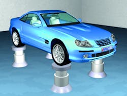
In other recent news related to HIL test, dSPACE announced last spring that its Automotive Simulation Models (ASM) now support the simulation of virtual test benches for vehicle dynamics analysis. The new ASM Kinematics and Compliance (ASM KnC) capability provides functions for designing and simulating wheel suspensions on a virtual test bench (Figure 2). Users now can run virtual tests for numerous vehicle variants and driving maneuvers to optimize vehicle suspensions and make them available for HIL applications.
Courtesy of dSPACE
The wheel suspensions are defined in a graphical user interface and exported as lookup tables for vehicle simulation models. The tool provides preset configurations for common suspension types: McPherson, double wishbone, and three-link, four-link, or multiple-link suspensions. ASM KnC is fully automatable so simulation results can be optimized to match real measurement data. The automation interface also can be used to forecast the individual properties of materials to meet higher target criteria for vehicle dynamics. Because the simulation parameters correlate directly with the real vehicle design, test engineers can optimize the vehicle dynamics behavior much more efficiently.
DAQ System for HIL
According to Bob Judd, United Electronic Industries’ director of marketing, UEI’s new DNF-4-1G FLATRACK Ethernet-based data acquisition (DAQ) and control platform (Figure 3) also can serve HIL applications. The FLATRACK is a highly integrated, low-profile DAQ I/O engine made to accommodate a growing need for greater system programmability, functional versatility, and scalable deployments. Developed in response to new market demands for a rack-mountable 1U chassis with high-density I/O capabilities, its low-profile footprint and user-friendly programmability set it apart from other rack-mounted systems, Judd said, adding, “For rapid prototyping, evaluation, and HIL testing, its advanced architecture and I/O flexibility make it suitable for a variety of next-generation DAQ applications.”
The DNF-4-1G FLATRACK provides two Gigabit Ethernet (100/10 Base-T compatible) interfaces and four front-loading I/O slots. More than 50 compatible I/O boards can be installed and interchanged for blended I/O architectures. The FLATRACK can accommodate up to 100 analog inputs, 128 analog outputs, 192 digital I/O bits, 48 ARINC-429 channels, four MIL-STD-1553 serial buses, and 32 RS-232/422/485 ports. Users can design, configure, test, and blend I/O channels to suit any sensor or interface requirement.
RF/Microwave Applications
While HIL test has traditionally been applied to automotive, military/aerospace, and large industrial applications, it also can find use in RF and microwave development projects. Such capability is available in recently released reference libraries for Agilent Technologies’ SystemVue platform for communications and aerospace/defense systems design.
Those libraries include the Global Navigation Satellite System baseband verification and Digital Modem libraries, which allow system designers and algorithmic researchers to bring instrument-grade standards references into design simulation early in the R&D process. Satellite and communications systems now can be verified under a variety of realistic impaired conditions, before baseband or RF hardware is available, enabling faster deployment of high-performance systems.
For example, satellite communications designers upgrading to higher data-rate systems require additional framing, synchronization, equalization, retraining, filtering, sampling, and direct-
sequence spread spectrum (DSSS) support. Lacking commercial tool support, designers typically handcraft custom toolsets for both simulation and test equipment.
Agilent’s Digital Modem library eliminates the need for this effort. It provides signal-processing reference models—complete with BER testing—for approximately 35 digital modulation formats used in satellite, military, and commercial wireless communications systems. The library also supports signal generation and measurement capture through SystemVue for HIL testing of digital predistortion, DSSS communications, and BER applications. Moreover, it enables different design personnel (for example, baseband and RF components designers as well as system architects and verifiers) to converge on a common reference for a wide variety of signal formats.


