Developing and testing battery-powered equipment
How long your cell phone operates depends entirely on how you use it and the battery’s state of charge (SOC). Talk a lot, and it will run for much less time than if you just receive a few text messages, regardless of the SOC. Nevertheless, if you have had an important call dropped because the battery’s charge became depleted, you know how critical SOC can be.
Designers of phones and other portable electronic equipment go to extreme lengths to save power. But to evaluate a new circuit’s performance, they don’t use batteries. They need a power source that is much better controlled and that allows them to explore corner cases such as a call being received with a nearly depleted battery. They use special power supplies that simulate an actual battery.
For many test applications, this means being able to vary the supply’s output resistance as well as voltage. Real batteries have internal resistance that changes as the battery discharges and as it ages. Nickel-based battery chemistry shows a relatively large variation in resistance vs. SOC, but lithium polymer cells have virtually constant resistance. The internal resistance of both types of batteries increases with age.
Hybrid and electric vehicle developers also have test flexibility considerations in addition to a range of very practical concerns. As Bloomy Energy Systems’ Jonathan Murray, the company’s business unit manager, commented, Bloomy’s Battery HIL Simulation System “provides a safe method to implement irregular and dangerous conditions such as shorting cells or creating over-current or thermal-runaway conditions—all tests you would not want to implement with a physical battery.”
In addition, Murray highlighted factors common to testing all battery-powered products. He said, “Because a physical battery degrades over time, there will be inconsistencies throughout the life of your testing if you use the same battery; if you use different batteries, there would be no correlation of data.” He also noted the benefits of battery simulation compared to the time and power required to charge a real battery.
Ed Brorein, applications specialist at Agilent Technologies, explained, “We have to be careful here to distinguish between a battery simulator power supply used to replace the function of the battery during test and a battery tester power supply used to perform battery charge/discharge management. While both are capable of sourcing and sinking power, these are basically opposite sides of a coin.”
With Brorein’s comments in mind, it is useful to highlight those instruments that can replace a battery in its intended application. These products must provide not just the correct voltage-SOC relationship, but also actual current and power levels as well as output resistance and speed of response.
Full-power simulation
Speed is a major factor in Keithley Instruments’ Models 2302, 2306, and 2308 battery simulator power supplies, which can simulate “the performance of a battery with ultrafast transient response, so they can have output characteristics identical to actual batteries,” according to Robert Green, senior market development manager at the company. He said, “Each source’s battery-simulator channel has a variable output resistance that can be programmed over the range from 0Ω to 1Ω with 10-mΩ resolution to simulate the internal resistance of the actual battery that powers a device during use. Their battery-simulator channels also can be programmed to operate like a discharged rechargeable battery, sinking current from a separate charger or from the built-in charger-simulator channel in the Models 2306/-PJ/-VS and 2308.”
Green continued, “These supplies employ a unique variable output resistance so the voltage output can emulate a battery’s response (U.S. Patent No. 6,204,647). They provide stable voltage outputs, even when a DUT makes the rapid transition from the standby low-current state to the full-power operating high-current state. In addition, they can monitor DUT power consumption by measuring both DC currents and pulse load currents.”
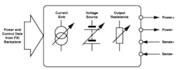
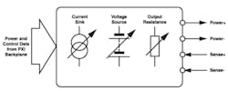
Fast transient response also is a feature of Pickering Interfaces’ Model 41-753 PXI Battery Simulator Module, which provides a single isolated output that can deliver 2.5 A at 6 V. With 2-meter lead length and using the remote sense feature, transient response is quoted as 15 µs. The module also can sink up to 0.5 A, and the output resistance can be programmed for values up to 1.15Ω (Figure 1).
Figure 1. Model 41-753 Battery Simulator Module Block Diagram
Courtesy of Pickering Interfaces
Herman van Eijkelenburg, director of marketing at PPST, parent company of Pacific Power and Adaptive Power Systems (APS), discussed various battery simulation solutions. He said, “APS’s line of programmable DC power supplies provides a standard internal resistance mode that allows the internal resistance of a battery to be simulated. The same feature may be used to model a battery by setting the Vth and Rth values for a Thevenin equivalent circuit to simulate various battery characteristics. To simulate the effect of polarization, which results in reduced battery life, the value of both parameters can be programmed as a function of time using the built-in scripting capability of the APS power supply.”
He continued, “Simulating fast current transients is possible when using a DC supply in combination with a programmable DC load with dynamic current programming capability. APS offers several families of high bandwidth electronic loads at power levels ranging from 75 W to over 60 kW. The combination of a DC power supply and electronic load allows a battery charge/discharge test system to be configured. To enhance the embedded measurement systems of the DC supply and DC load, an analog current monitor output is provided that allows current capture waveform in real time using a digital storage scope.
“Alternatively, APS also offers two-quadrant DC power supplies, which transition seamlessly between source and sink mode,” Van Eijkelenburg concluded. “To support sudden changes in current demand, both current delivery capability and current sink capability must be supported. The APS DPR line of two-quadrant DC supplies was developed specifically for such applications and comes in power levels starting at 5 kW and ranges to at least 90 kW.”
Emulation
In a short white paper, NH Research promoted the benefits of battery emulation, stating, “Batteries can be modeled as a bidirectional voltage source along with a series resistance…. The NH Research 9200 Battery Test System provides an electronically programmable battery emulation mode, allowing any battery to be simulated at any state of charge.”
Battery emulation requires having the correct output power, transient response, and voltage-current relationship for the type of battery being simulated. NH Research is among many companies using the term, but even for systems that satisfy these conditions, some companies may refer to battery simulation rather than emulation.
Agilent’s datasheet for the 66319A and 66321A Mobile Communications DC Sources highlights the benefits of fast transient response, remote sense, and built-in measurements. In addition, the 66319B/D and 66321B/D models provide programmable output resistance and advanced battery-drain measurements.
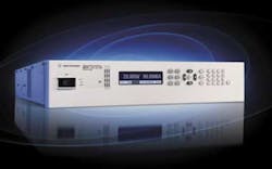
Under the subheading “Performs Like a Battery,” the datasheet states, “With their battery emulation features, the Agilent 66319B/D and 66321B/D allow you to test your devices under the same power conditions that exist in actual use. Emulating the battery is key when characterizing battery operating life and detecting early product failures. These DC sources simulate the effects of internal resistance of the battery, enabling them to emulate the operation of various battery types or batteries in different charge states. Plus, these DC sources can simulate negative resistance so that you can compensate for voltage drop due to wiring in a fixture.”The 663xx series supplies are rated from 40 W to 100 W. For higher power applications, the company’s Advanced Power System N6900 and N7900 series supplies are available in 1-kW and 2-kW models (Figure 2). The supplies use a seamless ranging technique to measure current from microamps to amps and can sink up to 10% of their rated output current. By adding one or two N7909A power dissipater units, current sinking can be increased to 100% for an indefinite time.
Figure 2. Model N6971A Power Supply
Courtesy of Agilent Technologies
Certainly, a battery used in portable electronic equipment has its own characteristics that a test setup must replicate. However, the amount of power involved is nothing like that associated with a hybrid or all-electric vehicle. For these kinds of products, supplies such as those from APS, AeroVironment, and Digatron Power Electronics are used during power-train development and test.
AeroVironment’s Power Cycling and Test Systems are rated from 30 kW (Model MT-30) to 250 kW (Model AV-900) and have been used to develop fuel-cell buses and hybrid locomotives. Digatron's Battery Emulator is listed at 80 kW and can be expanded to 400 kW. High-power battery emulators feature energy regeneration back to the AC line to improve efficiency.
Control Simulation
For battery management system (BMS) testing, full-power battery emulation is not necessary and may not be desirable. A much lower cost and safer approach is to use specially developed instruments such as the Bloomy Battery Simulator 1200.
As described by the company’s Murray, “The Bloomy Battery Simulator 1200 is a standalone instrument offering 12 independently controlled cell simulation channels with 1,000-V channel-to-channel and channel-to-ground isolation and auxiliary IO. Each cell provides 0 to 5 V DC output with ±500 mA of charge/discharge capabilities with integrated cell voltage and current readback. The Battery Simulator 1200 output channels are a four-wire configuration (±Vout, ±Vsense) with a voltage dynamic response at full load of ″150 µs, providing a robust output for battery simulation.”
Pickering also makes a multicell battery simulator, but as a PXI module. The Model 41-752 is a six-channel instrument with 750-V isolation, up to 300-mA output per channel, 100-mA current sink capability, and independent sense connections.
Both Bloomy’s 1200 and Pickering’s 41-752 are intended for use in BMS test systems. Individual cell performance within a large stack of cells can be programmed to explore how well the BMS maintains cell charge balance or copes with exceptions like a shorted cell.
Bloomy’s Murry commented, “The Bloomy Battery Simulator 1200 …[is] focused on testing control electronics, commonly known as the BMS and therefore can use low-power signals. Our instrument is uniquely designed with the capabilities to simulate multiple DC systems (because of the isolation), current sensors, and additional IO at high speeds to provide the low-power signals that are necessary to test the control electronics.”
He continued, “Our goal is to provide safe methods of simulating the cells and currents for evaluation of battery management systems. With this being said, the majority of BMS use external current monitoring techniques such as shunt resistors, Hall effect sensors, or other types of transducers. The Battery Simulator 1200 provides auxiliary analog and digital outputs, which can be used to provide the simulated signal.”
Bloomy’s Battery HIL Simulation System is based on the Battery Simulator 1200 units and a National Instruments PXI chassis including a real-time controller and the necessary IO cards for simulation of the BMS control signals and communications. The Battery HIL System software integrates NI VeriStand and can be used with custom battery models. A series stack of up to 200 cells can be simulated (Figure 3).
Figure 3. Battery HIL System Block Diagram
Courtesy of Bloomy Energy Systems
Choices
It’s important to understand whether you need to provide the same level of power that a battery would supply for a given application or if you only are testing the control circuitry. Or, are you addressing a different problem? When multiple types of power sources are brought together in a system, things can become complicated.
For example, National Instruments’ Brian MacCleery, principal product manager for clean energy technology at the company, described a recent power-related project. He said, “For fast real-time simulation of switched-mode power supplies containing battery storage and power electronics transistors, NI has been developing a new class of graphical floating-point real-time simulation solvers that execute in hybrid field-programmable gate array (FPGA) hardware. By ‘hybrid FPGA,’ I mean that the device is actually a heterogeneous system-on-a-chip containing an array of DSP cores intermixed with conventional programmable logic fabric.
“This provides an ideal chipset for fast real-time simulation, even for power converters with high switching frequencies as found in cell phones and similar consumer electronics devices,” he concluded. “These fast real-time simulation solvers can be used for signal-level simulations (no actual power flowing) or combined with special power supplies that replicate the power flow of the actual device, which enables comprehensive validation and verification that’s inclusive of test conditions that would be impossible to produce without simulation. These types of signal-level and full-power simulators are needed to achieve the reliability levels we expect of cell phones and other consumer devices.”


