Courtesy of ETS-Lindgren
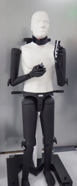
To make over-the-air (OTA) testing more closely represent the way wireless-connected devices actually are used, phantoms corresponding to all or part of a human body are needed. Several types of phantoms are available, such as POPEYE (POsable Phantom for Electromagnetic sYstems Evaluations) (Figure 1), photographed during a recent tour of the 7Layers facility in Sunnyvale, CA. 7Layers is a Bureau Veritas Group company experienced in wireless-device OTA testing.
POPEYE V5.5 is an anatomically correct human phantom made by SPEAG, a Swiss company, and based on a torso shell with a head, arms, hands, and legs. As described on the SPEAG website, “This radio frequency (RF) human has been designed to meet the requirements for test configurations for which the effects of the body on the EM performance cannot be neglected, such as operating tablet and laptop computers and other body-mounted transmitters. With a simple adjustment (one tightening screw), the arms, hands, and legs can be positioned accordingly for conducting simulations of any usage or operation (standing, sitting, arms raised, talking position, etc …).”
The larger parts of a phantom—the head and torso in particular—are hollow. To represent the average RF properties of bones and tissue, the head and torso are filled with a water and sugar solution described in IEEE 1528-2003 – IEEE Recommended Practice for Determining the Peak Spatial-Average Specific Absorption Rate (SAR) in the Human Head from Wireless Communications Devices: Measurement Techniques. Smaller parts, such as the hand and forearm, are made from silicone loaded with carbon powder. Although the RF characteristics of the water-based liquid and the silicone material are different, both are defined from 300 MHz to 6 GHz. In addition to the phantom itself, small fixtures may be required to hold the device being tested in a predefined position relative to the phantom. To avoid influencing test results, any fixtures should be made from material with a dielectric constant of less than 5.0 and a loss tangent of less than 0.05.
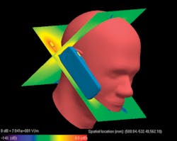
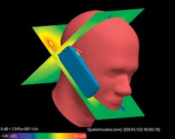
For several years, head phantoms such as the specific anthropomorphic mannequin (SAM) have been used to establish SAR values for cell phones. As explained on the FCC website, “SAR testing uses standardized models of the human head and body [phantoms] that are filled with liquids that simulate the RF absorption characteristics of different human tissues. To determine compliance, each cell phone is tested while operating at its highest power level in all the frequency bands in which it operates, and in various specific positions against the dummy head and body, to simulate the way different users typically hold a cell phone, including to each side of the head.”
7Layers, ETS-Lindgren (the tour sponsor), and 33 additional wireless industry companies recently developed version 3.4 of the Test Plan for Wireless Device Over-the-Air Performance: Method of Measurement for Radiated RF Power and Receiver Performance, an official CTIA certification program test plan. V 3.4 defines the use of a SAM-type head phantom together with a hand phantom and associated fixtures to more closely simulate how a user would hold and operate a phone in practice (Figure 2).
Courtesy of REMCOM
New test specifications
In addition to cell phones, 7Layers also tests wearable devices, which were the subject of a brief presentation during the tour by local 7Layers lab manager Clive Bax. As explained during the presentation, cellular carriers were becoming increasingly concerned about the validity of their tests. Before a series of new phantom-based procedures was proposed, the only requirement was for wearable devices to be tested in free space. Clearly, this condition did not reflect the influence of the user’s body upon device performance. For example:
- The user’s body absorbs energy depending on the body mass and permeability.
- Wrist-mounted products are influenced by location of the wrist relative to the user’s torso/waist.
- Ankle-mounted products also are influenced by the ground.
From data gathered by the CTIA M2M subgroup over a two-year period, it was clear that a large percentage of cellular products were body-wearable devices. The list included ECG heart monitors; medical patient monitoring bracelets; dog, sports, and prisoner tracking devices; and care worker badges. Most of the devices were classed as absorptive, but with percentages ranging from 2% or 3% to as high as 50%. Fashion wearables are yet another growing category, and the military also is using the technology.
Extending the head/hand phantom idea to include the effect of the user’s body represents a major change to the test specification, so it has been approached in phases. For wrist-worn devices, Phase 1 will make use of the SPEAG SHO-FPV2 forearm phantom, which has been approved by the working group.
To evaluate how well the phantom represented a typical user, a wrist-worn device was tested on 35 volunteers and on the SHO-FPV2 forearm. As noted in the 7Layers presentation, “Despite person-to-person variations of up to 5.7 dB in human wrist impact to measured TRP [total radiated power], the average human wrist impact agreed with that of the SPEAG forearm to about 0.1 dB.” Release of a test plan for wrist-worn devices is planned for October 2015.
Phase 2 will deal with medical devices, neck-worn devices including music players and medical pendants, and clothing-based devices. For this phase, use of a body torso phantom is anticipated, comprising the torso, head, arm, forearm, and hand.
For Phase 3, a full-body phantom such as POPEYE is needed. Clearly, this phantom could be used for Phase 1 and 2 tests as well, although the full body is not required. Currently, a POPEYE phantom is on loan to the working group for evaluation. A verification plan is being developed based on full-body devices.
Finally, a separate fourth phase has been proposed for head-worn devices that possibly could use the existing head phantom. Target devices include head bands, wireless ear-centric devices, eyewear, ear-embedded devices, and other head- and/or neck-mounted devices.
Test facilities
Anechoic chamber
As shown in Figure 3, 7Layers uses a large anechoic chamber for phone tests. Two test methods are described in V3.4 of the test standard: the conical cut method and the great circle test method. In the conical cut approach, the phantom and phone (EUT) are mounted on top of a turntable that can be rotated to successive positions in azimuth—the so-called Theta (Θ) angle. The field strength at angular positions in elevation—the so-called Phi (Φ) angle—is measured and recorded at 24 equally spaced positions for each Θ selection.
Courtesy of 7Layers
Rather than step through Θ positions, the great circle method rotates the EUT through all Θ positions for each successive Φ setting. For 15-degree steps, both the conical cut and great circle methods determine the field strength at 264 points on a spherical surface for each of two polarizations: 528 measurements in total.
Instead of repositioning a single antenna many times per test, 7Layers has attached 24 antennas around a ring of absorber material in the Φ plane (360 degrees). In addition, 12 antennas are placed in a semicircle of material in the Θ plane (180 degrees). Multiple measurements are made very quickly by switching from one antenna to another.
Reverberation chamber
In contrast to the minimal reflections present in an anechoic chamber, a reverberation chamber can accommodate users in a more realistic situation complete with reflections. For example, a manufacturer can evaluate the variation in performance that results from how the device is handled by the human user. The influence of having more than one person in the chamber can be tested. Coexistence of multiple devices such as a wrist-worn device, a pendant, and a phone or laptop computer can be explored.
As explained in an ETS-Lindgren press release following installation of one of the company’s reverberation chambers at the 7Layers Sunnyvale location, “Wearable devices’ connectivity can be positively or negatively affected by the wearer. The AMS-7200 OTA Reverb Test System is able to create a multipath environment to show antenna performance by simulating the effects of radio waves being diffracted or deflected from a body phantom representing human muscle tissue. 7Layers expects testing with this chamber to be a popular solution for the wearable manufacturers during the product development cycle. In addition to body phantoms, live human tests can be conducted inside the reverberation chamber to provide testing for the effects of different grip styles, body types, and movement on device connectivity.”
The press release continued, “The AMS-7200 OTA Reverb Test System can be used for certification testing of large form-factor devices. Reverberation chambers, because of the inherent multipath environment, overcome the requirements of a large quiet zone for testing in anechoic chambers. Reverberation chambers don’t have quiet-zone requirements, and if a device can be placed in the chamber, it can be tested. New product categories such as wireless appliances, teller machines, and automotive devices sometimes require a larger quiet zone and necessitate either an oversized anechoic chamber or a reverberation chamber to test to the certification requirements.”
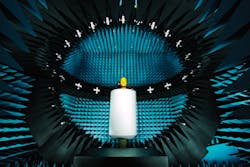
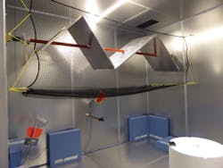
Figure 4 shows the smooth reflecting inner surfaces of the reverberation chamber along with the horizontal stirrer. A similar vertical stirrer is located in a corner not shown in this view. Without the stirrers, standing waves within the chamber result in an uneven field distribution. By slowly rotating the stirrers, the boundary conditions are sufficiently changed to produce a statistically uniform field strength throughout the chamber.
Courtesy of ETS-Lindgren
