“Gauging the strain,” February’s Special Report on Data Acquisition, presented traditional strain gage theory and highlighted several instruments and bridge amplifiers suitable for use with strain gages. This article identifies and reviews sources of in-depth strain gage information. Optical strain measurement is included.
HBM
If you work with strain gages, you will find Karl Hoffmann’s free 250-page book, An Introduction to Stress Analysis and Transducer Design using Strain Gauges, very helpful. Not only does Hoffmann explain how the various types of gages work, but he also includes a chapter on material properties and one on minimizing measurement errors.
In addition to providing a range of traditional metal-foil strain gages, HBM is a source of optical fiber Bragg-grating (FBG) gages. Because this type of gage relies on periodic variations in the fiber’s refractive index—the grating—FBGs are completely passive and immune to all EMI effects and can be used at a large distance from the interrogating instrument.
The HBM website includes a description of FBG gages and how they are made: “An FBG is a microstructure typically a few millimeters in length that can be photo inscribed in the core of a single-mode fiber. This is done by transversely illuminating the fiber with a UV laser beam and using a phase mask to generate an interference pattern in its core. This will induce a permanent change in the physical characteristics of the silica matrix. This change consists in a spatial periodic modulation of the core index of refraction that creates a resonant structure.”
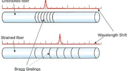
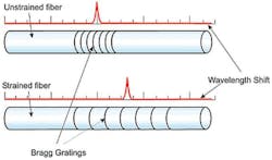
When the fiber is stressed, the wavelength of light reflected by the grating changes as shown in Figure 1. Both conventional and optical strain gage outputs are measured in µ-strain units. For the composite version of HBM’s Model FS62 FBG strain sensors, the measurement range is ±5,000 µ-strain with 1-µ-strain resolution when used with the FS22SI interrogator. The FS62 FBG operates at a central wavelength between 1,500 nm and 1,600 nm with reflectivity >65%.
FBGs also are sensitive to temperature changes. However, in contrast to strain, which physically stretches or compresses the fiber causing the elements of the grating to move, changes in temperature cause variations in the refractive index. This, in turn, affects the value of the reflected wavelength.
Micro-Measurements, a Vishay Precision Group brand
A very large amount of strain gage information is available from Micro-Measurements, organized as:
- Strain Gage Technology (Tech Notes and Papers)
- Application Techniques (Tech Tips and Application Notes)
- Product Usage (Instruction Bulletins)
- Technical Data for General-Use Strain Gages
- Technical Data for Transducer-Class Strain Gages
As an example of the depth of coverage, the first category contains 17 technical notes averaging from six to eight pages in length. Similarly, application techniques are explored in detail through 12 papers about bonding, a further three specifically on soldering, seven that focus on the treatment of lead wires, five more about bridge circuits, and a final paper covering the use of silicone RTV as a protective coating.
That Micro-Measurements should have an extensive understanding of the resistive metal foils used to make conventional strain gages is not surprising when you consider that similar technology is found in Vishay’s precision resistors. However, the company’s material science capabilities also extend to a range of PhotoStress products based on the optical behavior of strain-sensitive photo-elastic plastic.
As explained in a PhotoStress technology paper, 2 “Certain materials, notably plastics, behave isotropically when unstressed but become optically anisotropic when stressed. The change in index of refraction is a function of the resulting strain, analogous to the resistance change in a strain gage.”
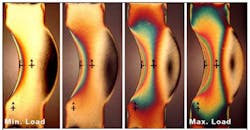
Rather than the single dimension associated with a Bragg grating that has been implemented within a length of optical fiber, PhotoStress sensors are two-dimensional patches of thin plastic that you stick to the DUT. Alternatively, the special plastic is available as a liquid that can be cast to conform to complex contours. When the plastic is stressed and viewed with polarized light, patterns such as those shown in Figure 2 can be seen. With increasing load, more fringes are visible, and each change in color indicates a certain amount of strain.
Courtesy of Micro-Measurements, a Vishay Precision Group brand
National Instruments
In addition to offering more than 600 types of modular instruments, NI provides a range of tutorials, white papers, and technical papers that can increase your technical knowledge. For strain gages, 20 detailed tutorials as well as 107 shorter specific discussions currently are available.
The seven-page “Load, Pressure, and Torque Measurements: How-To Guide” is typical of the tutorials and emphasizes a practical step-by-step approach rather than lots of theoretical background. Familiarity with NI LabVIEW and NI-DAQmx is assumed, and the tutorial progresses by showing the PC displays that you will see when following the how-to guide. An NI product and realistic strain gage values are used in the examples.
The 107 shorter “Knowledge Base” entries usually address specific issues. One entry deals with the question, “Can I Use Virtual Channels Instead of the SCXI Channel String When Nulling My Strain Gage Module?” According to an NI expert, “Virtual Channels cannot be programmatically changed in LabVIEW since they are first configured in Measurement and Automation Explorer. You must, therefore, use the full SCXI channel string when you are nulling your strain gage module using the SCXI Strain Null VI. However, if you choose to null your system in Measurement and Automation Explorer instead of in LabVIEW, you may use Virtual Channels.” The response also included an alternative work-around.
Precision Filters
Application notes, technical notes, white papers, and presentations are the headings available under the Papers and Briefs tab on the company’s home page. Of these, the white papers are the most technically oriented with only a small amount of product-specific content. For example, the paper, “Signal Conditioning Perspectives on Pyroshock Measurement Systems,”3 examines the specifications that a DAQ system must have to faithfully capture very fast and high-amplitude signals. As the authors note in the paper’s abstract, “In this article, we develop a systematic approach to determining how to use any low-pass filter to make valid shock measurements for subsequent shock response spectrum computations.”
Only one presentation currently is posted on the website, but it is an important one, equally applicable to many DAQ applications: “Ground Loop Problems with Measurement Systems and How to Avoid Them.”
United Electronic Industries
You can download the 200-page Applications Handbook from the UEI website. Although strain gages aren’t the primary focus, basic information about their use is included as well as a nine-page application brief that describes strain measurement with the AI-208 DAQ module. Just as the Precision Filter ground loop presentation was of general interest, so too are many of the other topics covered in the Applications Handbook.
UEI is one of a handful of companies manufacturing a strain gage simulator module. These instruments provide realistic and programmable outputs that mimic those from an actual strain gage and can be used to calibrate or troubleshoot systems configured for that type of input. The –QH version of the DNA/DNR-AO-358 eight-channel board supports half- and quarter-bridge configurations while the standard board is for full-bridge applications. For the 350-Ω unit, resistance changes as small as 1.33 mΩ can be programmed. The board also comes in 120-Ω and 1,000-Ω models, and other values are available on a special-order basis.
Pickering Interfaces
Model 40-26x PXI precision programmable resistor modules and similar model 50-26x PCI modules are available from Pickering. Types 40-265 and 50-265 are six-channel strain gage simulation units available in a range of standard resistances. As described in the 40-265 datasheet, “Each strain gage simulator includes an independent input for the excitation voltage and a bridge output to simulate a strain gage. The excitation voltage port can be driven by an AC or DC source. The bridge circuit includes three fixed resistors and a fourth programmable resistor that can be adjusted over a narrow resistance range with fine adjustment capability and excellent accuracy.” For the Model 40-265-016 350-Ω unit, the variable resistance can be changed by ±2%, and the programmable resolution is <2 mΩ.
Conclusion
Conventional strain gages have been available for decades, so it’s not surprising that a great deal has been written about their properties and use. Optical strain measurement is a newer technology, but it, too, is well represented in the literature. In most cases, the manufacturer of the device you are considering using is the best source of detailed information.
Research for this article only included material directly related to individual strain gages. This means that load cells, pressure transducers, and many other kinds of bridge-based transducers were not considered. There is similar performance data and application guidance available for these devices as well.
References
- Chavez-Pirson, A., “The Basics of Fiber Bragg Gratings,” Sensorsmag.com, August, 2004.
- Introduction to Stress Analysis by the PhotoStress Method, Micro-Measurements, Technical Note TN-702-2, June, 2011.
- Firth, D. R., and Szary, A. R., “Signal Conditioning Perspectives on Pyroshock Measurement Systems,” Precision Filters, 2013.


