Most electronic engineers know that a transistor’s base-emitter voltage (VBE) has a temperature coefficient (TC) of about -2 mV/°C. However, for precision temperature sensors, “about” isn’t good enough. A number of ingenious designs have capitalized on the basic relationship in ways that guarantee accuracy over the typical -50°C to +150°C range.
Analog Devices Inc. (ADI) and Texas Instruments (TI) have developed analog sensors based on the difference in VBE (∆VBE) for two transistors operated with different current densities. By working with ∆VBE instead of VBE, IS—the reverse-bias saturation current in the Shockley diode equation—is eliminated in the math, as shown in equation 1.1
In the ADI reference, the larger area is provided by N identical transistors operated in parallel while the TI description refers to two different size transistors.2
The TI reference also discusses an interesting refinement. “In order for the circuit to retain its accuracy over temperature, the leakage currents of each transistor, which can become quite significant at high temperatures, must be equal so that their effects will cancel one another…. To correct the problem, the circuit is built with Q1 and Q2 each replaced by a transistor group consisting of both Q1 [with 10x the emitter area of Q2] and Q2. These transistor groups have equivalent geometries, so that their leakage currents will cancel, but only one transistor from each group, representing Q1 in one group and Q2 in the other pair, is used in the temperature sensing circuit.”2
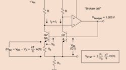
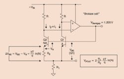
How the ∆VBE value is processed also varies. Figure 1 shows a simplified circuit that ADI has used to provide a 1.205-V bandgap voltage reference. The collector currents are forced to be equal by the op amp output that drives the transistor bases to a common voltage. This means that the current through R2 is equal to ∆VBE/R2. Therefore, the voltage across R1 is equal to 2x that current x R1, or
where VPTAT is the voltage output proportional to absolute temperature.
Courtesy of Analog Devices
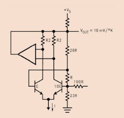
In contrast, Figure 2 shows an op amp used both to force equal transistor currents and to scale the output to 10 mV/°K. The 100-Ω resistor is used to add a second-order correction current.
Courtesy of Texas Instruments
Note that in Figure 1, Q2 has the larger emitter area, but in Figure 2, Q1 has the larger area. Nevertheless, both circuits leverage the difference of the base-emitter voltages. In Figure 1, ∆VBE appears directly across R2 between the two emitters, but in Figure 2, ∆VBE is measured across resistor R between the two bases.
In addition to developing a voltage or current directly proportional to temperature, some of these designs achieve a nominally zero-TC bandgap voltage reference output by adding VBE with a negative TC of about -2mV/°C to ∆VBE with a positive TC of about +2mV/°C. Bandgap circuits have an output voltage near 1.22 V—the bandgap voltage of silicon—and are used in designs for which the much higher voltage of a temperature-compensated zener is inappropriate.
The AD590 is a two-terminal sensor with current proportional to temperature in degrees Kelvin. The proportionality is factory trimmed to be 1 µA/°K, so at 0°C, the output current ideally is 273.7 µA.
The Linear Technology Corp. (LTC) LTC2996 temperature monitor also uses ∆VBE measurement as the basis of the temperature sensing circuit. However, instead of comparing the VBE of two different transistors, the LTC2996 switches the amount of current driving a single internal or external diode. Measuring the diode voltage at two currents is equivalent to the ADI or TI approach—the saturation current drops out of the equation. A third current can be switched to determine the diode’s series resistance, and a circuit is included to compensate for it. In common with the circuits of Figures 1 and 2, the LTC2996 has an output scaled per degree Kelvin—4 mV/°K in this case. The LTC2996 has a guaranteed temperature error ≤±1°C from 0°C to +100°C and ≤±1.5ºC from -40°C to +125°C.
When used with an external diode—for example, to measure the temperature on remote equipment—the LTC2996 provides a current output suitable for driving long lines. As described in a LTC article, “Series resistance up to 1 kΩ typically causes less than 1°C of temperature error…. the maximum distance is limited more by the line capacitance than by the line resistance. Capacitances larger than 1 nF start to impact the settling of the sensor voltage at the various sense currents and therefore introduce additional temperature reading errors. For example, a 10-m long CAT 6 cable has about 500 pF of capacitance.”3
ON Semiconductor also uses this approach and has developed both two-current and three-current devices. As you might expect, the two-current sensors are sensitive to series resistance so are best used for local temperature measurement based on the integrated diode. Like the LTC part, the three-current devices can compensate for series resistance, which is important in the automotive market. About half of the company’s thermal management products are called digital temperature sensors. However, even those that don’t have “digital” in the component description still contain a large amount of digital circuitry. It’s not clear than any have a truly continuous analog output proportional to temperature.
The company’s NCT475 device gives an idea of the sophistication that can accompany a digital temperature sensor. This IC uses a 12-bit delta-sigma ADC to develop a new temperature reading every 80 ms. The values are stored in bytes, so if your application requires only 8-bit resolution, you just need to read 1 byte. In addition, because the device draws about 500 µA from a 3.3-V supply, a one-shot mode allows you to make one temperature conversion and immediately revert to a shutdown mode that consumes 3 µA. The NCT475 is fully register compatible with the NCT75 (ON), LM75 (TI, Maxim), and TMP75 (TI).
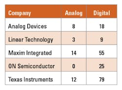
Maxim Integrated lists about 70 types of temperature sensors on its website, most of which have at least some digital circuitry. For the MAX6576, the output square wave period directly relates to absolute temperature. For the MAX6577, frequency is used to indicate temperature. And in the MAX6667, the delay between an input strobe and an output pulse is proportional to temperature. All of these devices have a few scaling selections. For example, in the MAX6576 you can scale the period to represent 10xT, 40xT, 160xT, or 640xT, where T is the temperature in degrees Kelvin. Table 1 includes five of these single-wire-output devices in the total of 14 analog sensors because their output is continuously variable.
Changing the scale
The TI reference discusses higher accuracy linearization and conversion from a Kelvin to a Centigrade or Fahrenheit temperature scale output. Rather than the simplified relationship used in equation 1, a more complete VBE model, attributed to National Semiconductor’s Robert Widlar, is given in equation 3.
The first two terms in the equation are linear, and the last two are nonlinear. Working with just the linear terms, it follows that
where VG0 is the bandgap of silicon, typically 1.22 V; Ve is the emitter voltage in Figure 2; and 273.7 is the Kelvin equivalent of 0°C. During the derivation of this result, an equation was solved at T = 0°C—the reason the 273.7 number appears. Nevertheless, as the TI reference states, “… the rate of change of Ve with respect to temperature will be a constant, independent of the value of Vb [the transistor’s base voltage], the transistor’s beta or Vbe.”
To complete the design, the two small nonlinear terms are approximated by a separate compensation circuit that provides a current proportional to the square of IPTAT, a current proportional to absolute temperature. The LM35 sensor incorporates many of these ideas and features 10-mV/°C sensitivity and ±0.75°C accuracy from -55°C to +150°C with no external adjustment required.
Product trends
The analog circuitry required to perform accurate wide-range temperature sensing has been refined over several years and supports both a range of analog-output sensors as well as several digital-output sensors. Table 1 lists the number of both types of sensors currently available from each of the companies highlighted in this article. Although the number of digital sensors appears to be much higher than the number of analog ones, many digital sensors are similar except for different output formats.
References
- Linear Circuit Design Handbook, Analog Devices, Chapter 3, 2008.
- AN-460 LM34/LM35 Precision Monolithic Temperature Sensors, Texas Instruments, Application Report SNOA748C, May 2013.
- Schwoerer, C., and Trampitsch, G., “High Accuracy (±1°C) Temperature Sensors Improve System Performance and Reliability,” Linear Technology Journal of Analog Innovation, Vol. 22, No. 4, January 2013.
Editor’s Note
This article is based on information available on various vendor websites at the time of writing. Including details about a technique described by one company does not imply that other companies do not also use that approach. The intention in presenting the particular products and circuit highlights is to show both the theory underlying semiconductor temperature sensors as well as many of the variations commercially available. Although five prominent companies have been included in this article, that does not imply that other companies do not produce temperature sensor devices or that the quality of those parts is in any way inferior.
For more information


