DC electronic loads have been available for electronic testing applications for several decades. Today’s products include switched resistors, high-speed active loads utilizing power semiconductors, and regenerative loads that return power to the utility. Each technology group finds its way into various applications. This article describes some advantages and disadvantages of the technology alternatives and presents a newly developed, hybrid circuit topology offering some unique performance features.
Switched resistive loads
The oldest generation of electronic loads is based on the switching of resistive components. Depending on the power level, resistors are commonly constructed from steel plates, nichrome wire, or metal film. Switched resistor loads have the lowest cost per watt, but the poorest performance in terms of dynamic response, programmability, and protection.
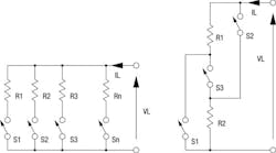
Figure 1 shows two circuits that are commonly used with resistive switching. The two configurations differ in their ability to select the desired resistor combination versus the ability to dissipate power.
Figure 1a, binary switching, provides the most accurate resistance selection per quantity of components. Resistor R2 has twice the resistance as resistor R1, R3 has twice the resistance as R2, and so forth. This circuit is often used in low-power applications to obtain digital-to-analog conversion where power is not a consideration. Power varies as the square of applied voltage, and as a load, binary switching exhibits poor performance in terms of power dissipation at lower voltage levels. Binary switching is the best choice for applications when the applied voltage is fixed.
Figure 1b, optimized power switching, allows resistors to be placed in series or parallel, offering better power-dissipation performance over a wider range of applied voltage. The disadvantage, when compared to binary switching, is that optimized power switching has a lower selection of available resistor settings per number of components. With three switches, maximum-rated power dissipation can be achieved at half- and full-rated voltage. Other resistor configurations are also possible by modulating resistor on-states with the available switches.
In DC systems and when using contactors for the switching devices, performance is usually limited by the contactor DC current rating. For cost reasons, AC contactors are commonly used for switching resistor elements, but with these devices, switching is restricted to low voltages where arcing can be minimized. This limitation prohibits the use of contactor-based switching for high-power dynamic load applications. In addition, DC contactors, while available, are rarely used because of cost and size constraints. Utilizing power semiconductors as the switching elements eliminates the constraint imposed by AC contactors, but are rarely used in favor of MOSFET load technologies.
Most electronic loads using resistive elements are fabricated by end-users wanting high-power, low-cost solutions for their testing needs, sacrificing dynamic loading and programmable protection capabilities.
MOSFET loads
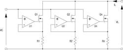
Metal oxide field effect transistors (MOSFETs) can be deployed as state-of-the-art electronic loads to address the limitations of resistor-based loads. As illustrated in Figure 2, these electronic loads use semiconductor devices, operated in the linear region, to allow full power and full control over the entire VA rating of the product. MOSFETs have to be specifically rated to operate in the linear region and have safe operating curves well below the maximum power rating when used as an electronic switch.1, 2 Circuitry for MOSFET loads requires each stage to be controlled in a closed loop to linearize the response. As shown in the figure, each device produces a load current defined by VC/Rn. Closed-loop amplifiers enable multiple MOSFETs to share load current equally. In addition, MOSFET loads have a fast dynamic response.
Regenerative loads
In the past decade, regenerative loads have started appearing as a viable product. A regenerative load is, in a simplified sense, an AC to DC power supply with power circuitry reversed to allow current flow in the reverse direction. Response times are similar to that of DC power supplies, and special circuitry is needed to stop operation in the event that the power mains voltage is disrupted for any reason. Regenerative loads can be compared to solar inverters as far as performance with exception to the DC range of operation. Like switched resistor loads, obtaining maximum power operation over a wide voltage range requires special circuitry rated at maximum voltage and maximum current; such performance demands can greatly increase the cost, as compared to a conventional switching power supply.
The major benefit of regenerative loads is that energy used for testing can be recovered. Some regenerative loads are designed to operate as both a source and sink. These products, regenerative power supplies, must have a dual set of electronic switches.
Using regenerative loads in pulse current applications is not recommended because any pulse-current at the input must flow through the unit and appear on the power mains. The economics of regenerative loads must be evaluated in terms of capital equipment costs versus energy savings.
Active resistive loads
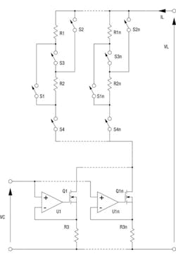
Active resistive loads are a blend between switched resistor loads and MOSFET loads. The advantage of resistive loads is cost per watt of dissipating power, and the advantage of MOSFET loads is speed of performance and the ability of dissipating power over a wide range of control. Figure 3 shows the basic concept of an active resistive load.3 As illustrated, a critical part of the design is that resistors are placed in series with MOSFETs. MOSFETs are voltage-to-current, transconductance devices. Voltage perturbations resulting from resistors switching are compensated with reverse voltage perturbations across the MOSFETs. Amplifiers, used to share current between devices, do not need to respond quickly to these voltage changes because of the profile of MOSFET devices when operated as a transconductance device. A constant gate voltage in the device’s active region provides nearly a constant current.
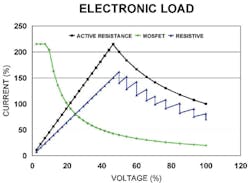
The range of maximum power loading, like in resistive loads, depends on the number of resistors, number of switches, and applied voltage. To compromise between the number of dissipative elements and range of maximum power loading, both resistor configurations as described in Figure 1a and 1b are applied. Careful design of the cooling system can enable maximum power output over half-rated to full-rated voltage. With sufficient number of resistor switching states, power dissipation can be shared with an 80% to 20% ratio for resistor-to-MOSFET power dissipation, respectively.
Below half-rated voltage and as described previously, maximum power dissipation varies as the square of applied voltage. Having a series MOSFET connection enables a broader profile for lower voltage applications. This requires the resistor elements to be shorted. If the maximum power is limited to 20% of the total using the MOSFET section of the load, this part of the load can provide a 20% maximum power profile. While this is not ideal, it is an effective compromise when considering the cost benefit.
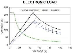
With the MOSFET section of the load shorted, the electronic load becomes purely resistive, and the load is operated in rheostat mode. While this could be considered a downgraded load, there are many applications where a purely resistive profile, with no closed-loop control, is desirable. The dynamically switched resistor states eliminate the possibility of two closed loops, that of the source and load, to operate against one another. Bandwidth for step changes in resistance depends on the speed of the resistor switches. The active resistive load can provide 80% of the load’s power rating over a range of half-rated to full-rated voltage.
Figure 4 illustrates the load profiles of MOSFET, resistive, and active resistive operation.
Robustness is a key characteristic of active resistive loads. Current limiting is constantly enabled with a series-connected resistor. A sudden demand change in current will cause the MOSFETs to saturate, protecting the devices from exceeding their safe operating area.
Balancing power between the resistors and MOSFETs presents one of the key challenges for effective active resistance load operation. The MOSFETs must have a range of voltage to offset the voltages produced by the switching resistors. Load voltage and current must constantly be monitored to provide resistor state changes along with analog control of the MOSFETs. High-speed digital signal processors (DSPs) are required to make such calculations to ensure proper operation. Step load responses require feed-forward compensation to force a change in resistance prior to changing load current with the MOSFETs. If step changes in resistance are made quickly and the MOSFETs are made to respond soon after, MOSFET safe operating area can be maintained for reliable operation.
Conclusion
This article provides an overview of electronic loads currently available, namely switched resistance, MOSFET, regenerative, and the newly introduced hybrid, active resistance. Each load topology has advantages and disadvantages, ranging from cost and speed of operation to loading as a function of applied voltage. The active resistance topology has characteristics of switched resistance and MOSFET loads combined, as well as operating independently of the others.
References
- Sattar, Abdus, and Tsukanov, Vladimir, “MOSFETs Withstand Stress of Linear-Mode Operation,” Power Electronics Technology, April 2007, pp. 34-39.
- Dodge, J., “How to Make Linear Mode Work,” Bodo’s Power Systems, December 2007.
- Pitel, I., Pitel, G., and Pitel, A.. “Electronic Loads,” U.S. Patent No. 9,429,629.
About the author
Ira J. Pitel received his B.S. degree from Rutgers, The State University of New Jersey, his M.S. degree from Bucknell University, and his Ph.D. degree from Carnegie-Mellon University. From 1973 to 1976, he worked for GTE Sylvania researching high-frequency ballasting techniques for gaseous discharge lighting. He joined Bell Laboratories in 1978 and Exxon Enterprises in 1979. At Exxon, he was involved in high-power converter structures for AC motor drives and controlled lighting. In 1981, he founded Magna-Power Electronics.
Ira holds 29 patents in the field of power electronics and is corecipient of the 1995 Society Prize Paper Award of the Industry Applications Society. He was honored as the Rutgers Outstanding Engineering Alumnus in 2000. He received the 2008 Gerald Kliman Innovator Award. He is a Fellow of the IEEE and has served in many IEEE capacities, including Society President of the Industry Applications Society. He is a member of the Eta Kappa Nu and Tau Beta Pi.
