Understanding Phase-Noise Measurement Techniques
This article appeared in Microwaves & RF and has been published here with permission.
Members can download this article in PDF format.
What you’ll learn:
- Measuring phase noise with a spectrum analyzer.
- The primary advantage of dedicated phase-noise analyzers.
- The cross-correlation method.
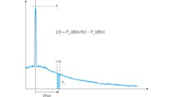
Using a spectrum analyzer is the oldest, most straightforward, and most widely used means of measuring phase noise. The basic procedure (Fig. 1) starts with measuring the carrier power (Pc) of the device under test (DUT) as an absolute value in dBm. The next step is to move to a given frequency offset from the carrier—that is, to a point in the phase-noise sideband. Then, you’d measure the noise power (Pn) contained within a 1-Hz bandwidth at this offset.
Subtracting the carrier power (Pc) from the noise power (Pn) yields phase noise in units of dBc/Hz at the given offset. In almost all cases, this procedure is repeated at different offsets from the carrier with results presented graphically and/or as individual-spot noise values.
However, when making phase-noise measurements using a spectrum analyzer, two additional steps must be performed to ensure accurate measurement values: normalization and shape correction.
Normalization
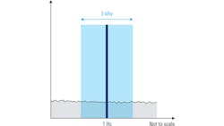
Phase noise is specified as the noise power contained within a bandwidth of 1 Hz. Spectrum analyzers measure power using a resolution-bandwidth (RBW) filter, and in most spectrum analyzers, the filter used to measure power is more than 1 Hz wide. Therefore, noise power measured by these wider RBW filters must be normalized to a 1-Hz bandwidth.
Such normalization is accomplished by reducing the measured noise power value by N dB, where N = 10 log (RBW in Hz). For example, if noise power measured with a 3-kHz resolution bandwidth filter is –90 dBm (Fig. 2), the normalized 1-Hz noise power would be –124.77 dBm (–90 – 10 log (3000)).
Shape Correction
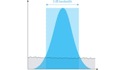
In Figure 2, RBW was shown as a rectangle. However, real-world resolution bandwidth filters aren’t perfectly rectangular; they usually have a Gaussian or similar shape (Fig. 3). So, in addition to normalizing the bandwidth, corrections must be made to compensate for the shape of the filter.
For a given resolution bandwidth, a Gaussian filter will have a wider noise bandwidth than its nominal (3 dB) bandwidth. Therefore, filter bandwidth must be multiplied by a scaling or correction factor before normalization. This correction factor depends on the specific filter implementation—not all Gaussian RBW filters have identical shapes.
For example, the shape correction for the 3-kHz filter shown in Figure 3 is 1.165, so when calculating N, the nominal filter width is multiplied by 1.165 before taking the logarithm. Note that most spectrum analyzers automatically apply both types of correction—bandwidth and shape—by means of a special noise marker function.
Measuring Phase Noise with a Spectrum Analyzer
This type of noise marker could be used to manually make phase-noise measurements. The marker would simply be placed at the offset of interest to obtain the normalized and shape-corrected phase-noise value. However, like most other manual processes, measuring phase noise in this fashion is both time-consuming and error prone.
Many modern spectrum analyzers have a phase-noise-measurement personality that automates the process and repeats the measurement over a user-defined range of frequency offsets. Spectrum analyzers are general-purpose instruments, so the greatest advantage of using a spectrum analyzer to measure phase noise is that it provides additional useful functions for characterizing sources, such as measurements of spurious emissions, settling time measurements, and many others.
Spectrum Analyzers’ Challenges and Limitations
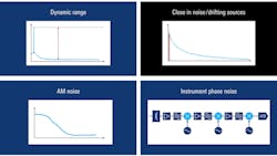
For many applications, the traditional spectrum-analyzer approach is sufficient for obtaining accurate and repeatable phase-noise measurements. It is important, though, to be aware of some of the challenges or limitations when using the spectrum-analyzer method (Fig. 4). These include dynamic range, close-in noise or drifting sources, AM or amplitude noise, and the contribution of instrument phase noise.
Dynamic Range
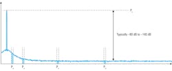
In using the spectrum-analyzer method, phase noise is calculated by measuring both the power of the carrier as well as noise powers at different offsets from the carrier. The difference between the measured carrier power and the measured noise power is usually quite large, typically from 80 dB to over 140 dB (Fig. 5).
Therefore, to make accurate phase-noise measurements, the analyzer must be able to measure both very high and very low powers simultaneously. As a result, dynamic range—the difference between the largest and smaller signals that can be accurately measured—becomes an important consideration when selecting a spectrum analyzer to make phase-noise measurements.
Close-in Phase Noise/Drifting Sources
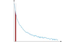
Measuring phase noise at very small offsets from the carrier (“close-in” phase noise) is challenging for two reasons. First, a very narrow resolution bandwidth is required to avoid measuring the carrier power as well as the noise power (Fig. 6). The fact that resolution bandwidth filters have a Gaussian rather than a perfectly rectangular shape also complicates this issue.
An additional challenge is measuring the phase noise of a carrier that drifts slightly in frequency. However, some analyzers do have the ability to track a small amount of drift and automatically compensate for it.
Modern spectrum analyzers can avoid some of these issues by measuring phase noise using so-called “I/Q data.” I/Q data is a digital representation of the spectrum and is obtained by means of the fast Fourier transform. Measuring with I/Q data can improve both the stability and the accuracy of phase-noise measurements, particularly for close-in or drifting sources.
Amplitude Noise
This same I/Q mode is also useful when it comes to amplitude (AM) noise. When measuring phase noise, it’s assumed that the noise sidebands around the carrier are mostly due to phase noise, with some smaller amount of amplitude noise mixed in. In general, this is a valid assumption: the AM noise in real-world devices is usually much less than the phase noise.
In some cases, though, this assumption may not be true. And if a relatively large amount of amplitude noise is present, the spectrum-analyzer method may not produce accurate results, because this method can’t normally distinguish between AM and phase noise.
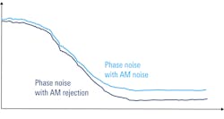
Separate measurements of AM and phase noise usually require the use of a different instrument—a dedicated phase-noise analyzer. However, a traditional spectrum analyzer can reject some AM noise if the measurement is made with I/Q data (Fig. 7). It should also be noted that the influence of AM noise is usually greatest at higher-frequency offsets from the carrier, so the benefits of using I/Q data become more noticeable with increasing offset from the carrier.
Instrument Phase Noise
An additional consideration is the phase noise of the analyzer itself. Spectrum analyzers usually contain multiple local oscillators (LOs). Like all other oscillators, the LOs used in a spectrum analyzer generate their own phase noise, and the phase noise of the LOs in the spectrum analyzer is added to the phase noise of the measured signal as it moves through different stages in the analyzer (Fig. 8).
Thus, one of the limitations of the spectrum-analyzer method is the difficulty in separating or distinguishing the phase noise present in the original signal from the phase noise added by the instrument. The easiest and most common way of avoiding this issue is to ensure that the analyzer has a better phase-noise specification than the DUT. At least 10 dB is generally considered the minimum acceptable margin, but a larger margin will provide more accurate phase-noise results.
There are many different methods for measuring phase noise. Some of the more common methods are the spectrum-analyzer method discussed above, the phase-locked-loop (PLL) method, and both phase-detector and digital phase-demodulator methods. Each of these methods has different strengths and weaknesses, but they all share the common limitation that phase noise from the instrument is added to the phase noise from the DUT.
Most of this added noise comes from the instrument’s local or reference oscillator(s). Such noise is problematic because it makes it difficult to determine how much phase noise is present in the DUT signal and how much is added by the measuring instrument.
As mentioned above, the traditional way of dealing with this issue is to use an instrument that has “better” phase-noise performance than the DUT, with “better” usually being defined as at least 10 dB or more down. However, this approach still may not be sufficient when measuring modern DUTs with very low levels of phase noise.
DUT Phase Noise vs. Instrument Phase Noise
Figure 9 illustrates the issue of instrument phase noise. The DUT has a certain amount of phase noise to be measured. Within the measuring instrument, this signal is processed using one of the different phase-noise measurement methods.
Regardless of the method used, processing or measuring the signal requires at least one local or reference oscillator; the phase noise of this oscillator is combined with the DUT phase noise. Depending on the relative levels of the phase noise in the DUT and reference oscillator, the resulting phase-noise measurement results may not be an accurate measurement of the DUT phase noise.
Improving Phase-Noise Measurements
Phase-noise measurement results can significantly improve by using an instrument whose local oscillators have low phase noise and employing a modern phase-noise measurement method, such as digital phase demodulation. However, such improvements still may not be sufficient for measuring very “quiet” oscillators.
In such cases, being able to remove, or at least reduce, the influence of instrument phase noise would be particularly advantageous, increasing sensitivity to very low levels of phase noise. Since the 1990s, cross-correlation has been the primary method for reducing or removing the effect of instrument phase noise.
What is Cross-Correlation?
Cross-correlation is a measure of the similarity between two different series or signals. It can also provide the time delay needed for maximum similarity. Cross-correlation is very widely used in many different signal-processing applications, such as radar and direction finding.
Because cross-correlation identifies the similarities between two signals, it can be used to reduce or remove the “differences” between sets of data, too. In other words, cross-correlation is able to separate data into “correlated” or similar parts and “uncorrelated” or dissimilar parts.
In addition, cross-correlation can be performed as an iterative or repeated process: Performing repeated cross-correlations more clearly separates the correlated and uncorrelated elements in two sets of data.
Cross-Correlation in Phase-Noise Measurements
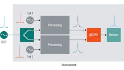
Because cross-correlation involves measuring the similarity of two different signals, it’s implemented by adding a second measurement path to the measuring instrument. The signal from the DUT is split and processed by these two nominally “identical” paths. Because the DUT signal is simply being split, the DUT phase noise remains the same or “correlated” on each path.
However, each path uses its own independent local oscillator for measuring phase noise, and the phase noise introduced by these local oscillators is thus uncorrelated or "different" on each path. Therefore, the measurement results from each path are a combination of the correlated DUT phase noise and the uncorrelated local-oscillator phase noise. When these two paths are fed into a cross-correlation function, the uncorrelated instrument noise is removed or reduced, leaving only the correlated phase noise of the DUT (Fig. 10).
Note that because of the need for two separate paths as well as the need to compare two sets of data, cross-correlation can only be implemented in dedicated phase-noise analyzers, not in traditional single-path spectrum analyzers.
About Correlation Count
Recall that cross-correlation can be performed iteratively or repeatedly. If the number of correlations, N, is increased, this will reduce the level of uncorrelated instrument noise in the measurement results. This, in turn, provides increased sensitivity or a lower noise floor, allowing for the accurate measurement of even very low levels of phase noise.
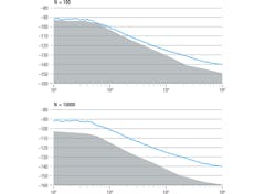
The improvement obtained by increasing the number of correlations is logarithmic and follows the formula 5 log10(N) dB. Every time the number of correlations is increased by an order of magnitude, sensitivity increases by 5 dB. For example, 10,000 correlations will lead to a 20-dB improvement.
Increasing the number of correlations will also increase the total time required for the measurement, but the benefits of cross-correlation normally far outweigh the relatively minor uptick in measurement time. Typically, the number of correlations used in phase-noise measurements ranges from several thousand to one million.
Visualizing Cross-Correlation Gain
The next question is how many cross-correlations to perform. The correlation count should be high enough to lower the instrument noise floor below the level of DUT phase noise, ideally with some margin to spare. This helps ensure that only the DUT phase noise is being measured.
In addition to the measured phase-noise trace, some phase-noise analyzers can also display the so-called cross-correlation gain, which may be used to visually verify the existence of sufficient measurement margin.
In Figure 11, the gray area beneath the phase-noise trace shows the cross-correlation gain. The higher the trace lies above this region, the more accurately the DUT phase noise can be measured separately from instrument noise. If the trace is too close to or touches this region, the instrument should be configured to perform a higher number of cross-correlations to further lower the measurement floor. In Figure 11, increasing the number of correlations from 100 to 10,000 clearly improves the measurement margin, particularly for phase noise at close-in offsets.
Summary
Phase noise can be measured using either traditional spectrum analyzers or dedicated phase-noise analyzers. The primary advantage of spectrum analyzers is that they’re general-purpose instruments and can be used for a wide variety of other measurements in addition to phase noise. However, the spectrum-analyzer method does have certain limitations that can make it unsuitable for measuring very low levels of phase noise or close-in phase noise.
Phase-noise analyzers utilize different types of specialized hardware to measure phase noise, but their greatest advantage is the ability to use the cross-correlation method. By applying a second measurement path, the cross-correlation method greatly reduces the influence of instrument phase noise and enables accurate measurement of very low levels of phase noise.
In some cases, phase-noise analyzers may also implement many traditional spectrum-analyzer functions, providing both enhanced phase-noise measurement sensitivity as well as standard spectrum measurements in a single instrument.

