Innovative Heat Flux Sensor Enhances Thermal Sensing and Measurement
What you’ll learn:
- Why heat flux (flow) is an important thermal parameter.
- How researchers have developed an innovative heat-flux sensor.
- Details on the performance of this sensor in flat and curved situations.
We know that temperature is a critical and informative parameter related to thermal energy, but it’s only one of several factors. Heat flux (sometimes called flow) measures how heat flows inside a material. It’s somewhat analogous to detailing current flow within (not just through) a conductor; as with current, it can be difficult to measure in situ.
Addressing this issue, a team based at the University of Tokyo set out to find a solution. Project Associate Professor Tomoya Higo noted, “Finding a sensor technology to measure heat flux, while also satisfying a number of other conditions, such as robustness, cost efficiency, ease of manufacture, and so on, is not easy. Typical thermal diode devices are relatively large and only give a value for temperature in a specific area, rather than an image, of the heat flux across an entire surface.”
Anomalous Nernst Effect
The team devised a heat flux sensor that exploits how certain special magnetic materials and electrodes behave when there are complex patterns of heat flow. The magnetic material, based on iron and gallium, exhibits a phenomenon known as the anomalous Nernst effect (ANE), which converts heat energy to an electrical signal.
(Note that the anomalous Nernst effect is far less well-known than the widely used Seebeck effect. The researchers said that the latter can actually create more electrical power, but it requires a large bulk of material, and these materials are brittle and thus hard to work. The ANE is the generation of a thermoelectric voltage transverse to the imposed temperature gradient and applied magnetic field in a ferromagnet. This effect enables magnetic metals and alloys to be exploited for heat-to-electrical-energy conversion.)
Use of the ANE allowed the team to engineer their device on a very thin and malleable sheet of plastic. They evaluated and selected the optimal magnetic and electrode materials and then applied them in a special repeating pattern, thus creating microscopic electronic circuits that are flexible, robust, cheap, and easy to produce. Most importantly, they’re all very good at outputting heat flux data in real-time.
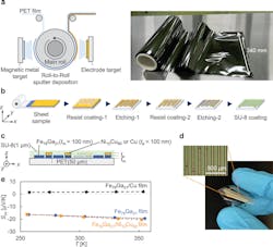
The method involves rolling a thin sheet of clear, strong, and lightweight polyethylene terephthalate (PET)—the common thermoplastic polymer resin of the polyester family—as a base layer, with magnetic and electrode materials sputtered onto it in thin and consistent layers (Fig. 1).
1. (a) Schematic illustration of the fabricating process employing the R2R sputtering system and photo showing the 340-mm-wide R2R fabricated thin films. (b) Schematics of the fabrication process for the ANE-based heat flux sensor. (c) Schematic illustration of the cross-sectional view of the heat flux sensor. The Fe79Ga21 and (Fe79Ga21/(Ni10Cu90 or Cu)) lines have a size of 15 mm length × 100 µm width (15 mm length × 40 µm width) with a distance of 10 µm, and the sensor consisted of 95 pairs of these elements. (d) Photo of the ANE-type flexible heat flux sensor on the PET substrate. The spots on the film are due to the anti-blocking layer on the film surface. (e) Temperature dependence of the Seebeck coefficient Sxx for each component of the heat flux sensor.
They then etched the desired patterns into the resultant film, similar to how electronic circuits are fabricated. The method uses sputtering and roll-to-roll (R2R) processes already employed in mass production, which can be easily applied to the fabrication of flexible and large-in-area heat flux sensors.
Seebeck Effect Gets in the Way
One of the challenges in the application of the ANE-type sensors is to remove the undesirable offset signal resulting from the electromotive force proportional to the difference in the Seebeck coefficient (ΔSxx) between the magnetic metal lines and the electrode lines.
In theory, this can be achieved in two ways: by adjusting the Seebeck coefficients of the magnetic metal lines and the electrode lines in conventional thermopiles, or by using single-material-based thermopiles with alternating magnetization directions via the time-reversal odd property of ANE. However, they said that the validity of this concept has never been demonstrated nor even investigated for perpendicular heat flux sensing using ANE.
Instead, the team designed the circuits in a special way to boost ANE while also suppressing the accompanying Seebeck effect that interferes with the data-gathering potential of ANE. Previous attempts to do this were unsuccessful in any way that could be easily scaled up and potentially commercialized, making this sensor the first of its kind.
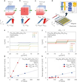
This first ANE-based heat flux sensor directly and selectively detects the perpendicular heat flux, where the Seebeck coefficients of the magnetic metal (Fe-Ga alloy) and electrode material (Ni-Cu alloy) in the sensor patterns are adjusted to be nearly equal. The sensor is specifically designed to eliminate the contributions from Seebeck effect voltages (ΔSxx ≈ 0). It also enables direct sensing of the perpendicular heat flux even in a practical situation where ∇T is applied in an oblique direction (Fig. 2).
2. (a-c) The magnetization (M) is aligned along the x-direction. V is the output voltage obtained in the experimental setup. EANE and ESE are the electric fields generated by ANE and SE, respectively. EANE(y) (ESE(y)) and EANE(z) (ESE(z)) are the y- and z-components of EANE (ESE), respectively. (d) Schematic illustrations of the transverse geometry of the heat flux sensor using ANE. VANE and VSE are induced by the temperature gradients in the perpendicular direction (∇Tz) and in the in-plane direction (∇Ty), respectively. The sensor signal is the sum of VANE induced in magnetic metal lines and VSE induced in electrode lines. (e,f) Magnetic field dependence of V for the ANE-type thermopile under various heater power at 300 K. (g,h) Zero-field sensor signal as a function of ∇Tz (blue circles) and ∇Ty (red circles) for the thermopiles at 300 K. The pairs of the Fe79Ga21 magnetic metal line and the Fe79Ga21/Cu electrode line (ΔSxx > 0), and the pairs of the Fe79Ga21 magnetic metal line and the Fe79Ga21/Ni10Cu90 electrode line (ΔSxx ≈ 0), are used in (e,g) and (f,h), respectively. ΔSxx is the difference in the Seebeck coefficient between the magnetic metal line and the electrode line.
This is in sharp contrast to the results obtained using the un-optimized sensor with ΔSxx ≈ 10 µV/K, which shows almost an order of magnitude larger ANE signal induced by the in-plane heat flux than that induced by the perpendicular heat flux.
Test and Evaluation
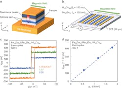
To evaluate the sensitivity of the heat flux sensor, they used the experimental setup to apply uniform perpendicular heat flux qz and temperature gradient ∇Tz similar to the previous reports (Fig. 3). The observed sensitivity was about an order of magnitude larger than the previously reported sensitivity for a Fe-Al flexible sensor of 0.02 µV/W-m2 (0.2 mV/W) and even larger than the sensors on the rigid substrates. Estimated sensitivity was 0.16 µV/W-m2.
3. (a) Schematic illustration of the experimental setup for the anomalous Nernst effect measurement for the ANE-type heat flux sensors. (b) Schematic design of the ANE-type heat flux sensors consisting of an alternating array of the Fe79Ga21 lines and the Fe79Ga21/Ni10Cu90 lines on the PET substrate. (c) Magnetic field dependence of the Nernst voltage VANE for the thermopile made of 95 pairs consisting of the Fe79Ga21 line and the Fe79Ga21/Ni10Cu90 line under the heat flux for the perpendicular direction qz = 0.56–1.78 kW/m2 at 300 K. (d) Zero-field VANE for the Fe79Ga21 and Fe79Ga21/Ni10Cu90 heat flux sensor as a function of qz obtained at 300 K.
To demonstrate the flexibility of the sensor, they also evaluated the sensor's sensitivity on the bending stage. The sensor was placed between a Cu heatsink with a curvature radius Rstage = 10.5 mm and a bending heater via thermal-interface silicone pads to apply the perpendicular heat flux qz = 1.78 kW/m2. Results were close to anticipated values.
Their work, from concept to implementation and fabrication, and test results, along with expected and unexpected problems encountered and overcome, is detailed in their nine-page paper “Roll-to-Roll Printing of Anomalous Nernst Thermopile for Direct Sensing of Perpendicular Heat Flux” published in Nature. A PDF version is also available here.
About the Author

Bill Schweber
Contributing Editor
Bill Schweber is an electronics engineer who has written three textbooks on electronic communications systems, as well as hundreds of technical articles, opinion columns, and product features. In past roles, he worked as a technical website manager for multiple topic-specific sites for EE Times, as well as both the Executive Editor and Analog Editor at EDN.
At Analog Devices Inc., Bill was in marketing communications (public relations). As a result, he has been on both sides of the technical PR function, presenting company products, stories, and messages to the media and also as the recipient of these.
Prior to the MarCom role at Analog, Bill was associate editor of their respected technical journal and worked in their product marketing and applications engineering groups. Before those roles, he was at Instron Corp., doing hands-on analog- and power-circuit design and systems integration for materials-testing machine controls.
Bill has an MSEE (Univ. of Mass) and BSEE (Columbia Univ.), is a Registered Professional Engineer, and holds an Advanced Class amateur radio license. He has also planned, written, and presented online courses on a variety of engineering topics, including MOSFET basics, ADC selection, and driving LEDs.


