The Benefits and Limitations of Ranging on Your Battery Tester
Members can download this article in PDF format.
What you'll learn:
- Definition of ranging for measurement systems.
- Single-range vs. multi-range systems.
- The basics of ranging operation.
In my previous articles “Benefits from Calibrating Your Battery Tester” and “Unraveling Measurement Accuracy Specifications for Battery Testers,” I discussed how to apply measurement accuracy specifications and how to determine the size of the error term when making measurements. When describing these topics, I referred to a measurement system, whether that be a standalone measurement device like a digital multimeter (DMM), or an integrated measurement function, such as the current measurement subsystem integrated into your battery tester.
These measurement systems can provide improved capability by offering multiple measurement ranges. To understand multiple ranges, let’s first look at single-ranged measurement system for simplicity.
For example, if you have a battery test system with a single-ranged current measurement system, the tester will have a single current measurement accuracy specification like ±0.2% of full scale. If this was a 100-A tester channel, then the full-scale range of the single measurement range is 100 A, and this specification would be ± (0.2% * 100 A) or ±200 mA.
With this specification, the measurement accuracy would have an error term of ±200 mA on any measurement made, from large currents of 100 A to small currents of milliamps. If you’re trying to measure very small currents, perhaps of 1 A or less, there will be a large error term compared to the value you’re trying to measure that’s caused by this fixed ±200-mA error term. This is the weakness of a current measurement system with a single range.
What is Ranging and How Does It Improve Measurement Accuracy?
To improve measurement performance, a multiple-range current measurement system could be used. In this case, the system could have the same current measurement accuracy specification of ±0.2% of full scale. However, because it’s a ranging system, the full scale would be different for each measurement range. You can switch ranges to match the range to the size of the measurement being made.
Often, the ranges are set up along decades, so this multiple-ranged 100-A current measurement system might have ranges of 100 A, 10 A, 1 A, and 100 mA. In each of these ranges, the offset error term would get 10X smaller because the range is becoming 10X smaller. Table 1 shows the offset error term on these ranges.
Thus, by selecting a smaller range when making smaller measurements, you can reduce the total error of the measurement.
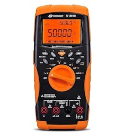
Likewise, if you were using a handheld DMM to measure voltage (Fig. 1), you would turn the range/function rotary switch to change the range to match the voltage you’re trying to measure.
How Does Ranging Work?
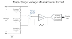
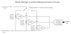
Now that I’ve explained ranging’s impact on measurements, let’s look at how ranging operates. Figures 2 and 3 below show schematic diagrams for a basic voltage measurement system with three ranges and a basic current measurement system with three ranges, respectively. Note that these aren’t complete design schematics but simplified to highlight the portion of the measurement system dedicated to ranges.
When measuring voltage, a set of resistors is configured as a voltage divider that’s used to scale the voltage down to match the input range of the analog-to-digital converter (ADC). The range switch changes the connections in the resistor network that adjust the scaling down of voltage. This enables the measurement system to utilize the ADC’s limited input range while the actual voltage to be measured varies widely.
When measuring current, the measurement system must convert the flow of current to a voltage and then measure the voltage. First, use a current sensor to sense the size of the flow of current.
The most common way to sense the flow of current is through a current-sense resistor, also known as a current shunt. The current to be measured flows through a calibrated current shunt inside the measurement system. As current flows through the current shunt, there’s a voltage drop across the shunt. This voltage drop across the shunt resistor is measured by the measurement system, which then calculates the current using Ohm’s Law (Voltage = Current * Resistance).
The size of the current-sense resistor is selected so that the full-scale measurement current flowing through the resistor creates a voltage drop (of perhaps 100 mV). Therefore, it can be easily measured by the ADC.
Another consideration is the heat generated in the resistor, which needs to be kept low or the current shunt can be damaged or go out of calibration. The heat in the resistor, in watts, is calculated by squaring the current flow and multiplying by the size of the resistor (Heat = Current ^2 * Resistance). Each range will have a different-sized resistor to scale the voltage.
Note also that when changing ranges, the measurement system must ensure that you have a make-before-break connection. If not, then the current flow will be interrupted as current will stop flowing when the range is changed.
Observing Improved Measurements Using Ranging
A ranging measurement system is a common way to provide the best accuracy with lowest error term for the measurements made over a wide range of voltage or current. In each range, the measurement system can be applied so that the full-scale range is most appropriate for the size of the measurement being made, thus reducing unnecessary error caused by large measurement ranges.
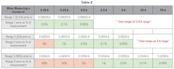
Table 2 illustrates the benefits of ranging for a battery tester with a current measurement system providing three ranges:
- Range 1 is 0.5-A Full Scale with an error specification of 0.05% of Full Scale.
- Range 2 is 5-A Full Scale with an error specification of 0.05% of Full Scale.
- Range 3 is 50-A Full Scale with an error specification of 0.05% of Full Scale.
For the 50-A range, if you’re trying to measure 2.5 A or less, the error exceeds 1% of the measurement. This isn’t the best range to make the measurement. Ranging down to the 5-A range would greatly improve the measurement performance by lowering the error. But again, if trying to measure 250 mA or less, ranging down to the 0.5 A range is advisable.
Closing Thoughts: Limitations of a Ranging Measurement System
Some multi-range measurement systems can also automatically sense the size of the value being measured and then automatically switch to the appropriately sized range. This function is known as autoranging, and it’s quite common.
While autoranging may seem to be the best approach when the measured parameter changes between large and small values throughout the battery test, there’s an important consideration: If the error term is different on different ranges, you must know on what range the measurement was made to know the error term.
With most autoranging systems, you don’t know on what range the measurement was made because it keeps changing. Moreover, it takes time for an autoranging system to switch between ranges, and any measurements will be lost during the switching time. So, when knowing the error term is critical and/or when you can’t afford to miss a reading, it’s best to avoid using autoranging and instead explicitly set the measurement system to the appropriate range.
Ranging measurement systems, as shown in Figures 2 and 3, are more complex than a single measurement range. With more components and more control logic to manage the ranges, the ranged measurement system is more expensive than a measurement system with single measurement range. Also, the costs to calibrate a multiple-range measurement system are higher, because each measurement range will require a calibration procedure.
