Engineering Essentials: What is Power-Supply Accuracy?
Members can download this article in PDF format.
What you’ll learn:
- How accuracy is defined in DC programmable power supplies
- How and why the power supply experiences voltage output errors
- How to wire test leads and sense leads for accurate measurements
When testing electrical and electronic devices, accuracy is the name of the game. In a manufacturing or design test situation, high precision is critical for product development, production quality, and, ultimately, customer approval of the final product. The accuracy of a test setup is influenced by many factors, including the choice and arrangement of instruments as well as the configuration and type of wiring used.
The key is the precision of DC programmable power supplies, which play a pivotal role in the overall accuracy of the test system. Like an archer aiming an arrow, an engineer who permits a tiny error at the source can see large errors in their results. Measurement accuracy depends on the DC power supply’s accuracy specifications, how the power supply monitors its output, and how it’s wired to the device being tested.
This guide explains the factors that impact the accuracy of DC programmable power supplies and provides tips for avoiding measurement errors.
Back to Basics: Understanding Power-Supply Accuracy
Accuracy can be defined on a datasheet in several different ways. Even experienced engineers can get confused when trying to choose a DC programmable power supply. These are the primary ways to define a power supply's output accuracy:
Display accuracy: Often the main factor affecting a power supply's precision, display accuracy quantifies the allowable error across the output and feedback paths. Since it encapsulates the accuracy of the DC output, it’s usually presented as a percentage of the full scale or the set output voltage. As electronic devices themselves, DC programmable power supplies are limited by the tolerances of their components.
Load regulation: This specification describes how the power supply maintains the output voltage under varying load conditions. Load regulation is expressed in terms of the full-scale or set output voltage. The components in a power supply have resistance, causing a voltage drop. High current loads exacerbate the effect. For a complete understanding of output accuracy, the engineer should add the load-regulation error to the display accuracy.
For more insights, check out Electronic Design’s special report on programmable DC power supplies.
Stability: Defined over a specific timeframe, stability reflects the permissible percentage variation of the full-scale voltage over time. Poor stability can be caused by factors like component tolerances, internal voltage drops, noisy ground currents, oscillation in the supply-load circuit, and temperature fluctuations.
If the ambient temperature is different from the specified temperature range for operation, then some manufacturers may provide a temperature coefficient to add to the output tolerance. It’s worth noting that stability is different from drift, which is measured over longer periods of time, such as 30 or 90 days.
Noise: Noise manifests as high-frequency voltage spikes on the programmable power supply’s output voltage. No matter how good it is, a DC programmable power supply will cause noise on the output, resulting in random voltage variations. Ripple arises from the imperfect conversion of AC power to DC power. While most programmable power supplies can filter out much of the ripple, it can’t be eliminated.
Other sources of power-supply noise include conditions on the AC line that may be common in some factory settings, EMI-induced noise, and stray currents on ground lines. Specifications may list root-mean-square (RMS) values, peak values, or both.
To illustrate these definitions, here are the specifications for a 200-V, 70-A, 5000-W DC programmable power supply, the EA Elektro-Automatik PSI 10200-70:
- Display accuracy: ≤ 0.05% of full-scale voltage
- Load regulation: ≤ 0.05% of full-scale voltage
- Stability: ≤ 0.02% of full-scale voltage
- Ripple (RMS): ≤ 40 mV
Considering a worst-case scenario where these inaccuracies accumulate, the total output accuracy of the power supply shows a maximum error of 280 mV for a 200-V output. This corresponds to a 1% error at 24 V DC, with the error decreasing as the output voltage increases.
The Role of Remote Sensing in Programmable DC Power Supplies
The design of the DC programmable power supply can influence accuracy in other ways. The effectiveness of any power supply in a test system depends on its ability to maintain voltage tolerance at the load. Some DC programmable power supplies measure voltage locally at their output and feed that value to the electronics that control the output. The power supply raises its output to compensate for the voltage drop.
Unfortunately, this approach fails to consider the voltage drop caused by the lead wires to the device being tested. Although lead wires may have low resistance, a significant load current in a long wire run can create a non-negligible voltage drop. Incidentally, the total voltage drop is twice that value, since there’s both a supply wire and a return wire.
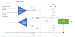
The solution is to measure the voltage at the load. Many power supplies use circuits that monitor the voltage at the load and feed the voltage value back to the power supply. This feature is called remote sensing (Fig. 1).
The Importance of Wiring for Accurate DC Power Measurements
Before testing even begins, engineers must take care in wiring to minimize voltage errors. This requires an understanding of the test circuit, as the wiring strategy differs depending on the type of load. For instance, using shielded twisted-pair wires for remote sensing can mitigate interference and potential voltage induction issues.
While remote sensing compensates for the voltage drop in the leads, there’s a limit to the magnitude of the voltage drop at which the power supply can maintain its accuracy. Typically, the maximum total voltage drop in the leads must be lower than 5% of the nominal output voltage. For example, if the output voltage is 24 V DC, then the voltage drop in the test leads must not exceed 1.2 V. Engineers should keep test leads short and avoid under-sizing the wires.
To learn more, check out Electronic Design’s product roundup of the latest bidirectional power supplies.
Remote sensing itself can contribute to noise and instability in the programmable power supply. Engineers should avoid noise on the sense line, which could cause the power supply to oscillate. Fortunately, this issue can be managed by using alternate wiring configurations selected for the capacitive and inductive characteristics of the load and test leads.
For a resistive load, engineers should keep the source leads and sense leads spaced apart. If there’s a nearby motor, employ shielded twisted-pair wire for the sense leads. This will minimize the loop area, preventing the motor's magnetic field from inducing a voltage in the leads (Fig. 2). Because the input impedance of the remote-sense circuit is high, small levels of electrical noise on the input could result in an error voltage.
The supply-load circuit is a complex impedance network, which can increase noise. Impedance, which is measured in ohms, is the opposition to electrical flow. While it’s a more complicated metric in AC systems, in DC systems, impedance is the same as the resistance on the power lines. This can be calculated by dividing the voltage by the current (R = V/I).
Oscillations can start in the sense circuit and propagate into the source output. Even routine events in automated test sequences, such as a step change in program voltage, can induce oscillation on the DC power lines.
To mitigate such risks, it's important to carefully design the sense circuit and employ proper wiring techniques. The solution is to place each sense wire next to its corresponding source wire. In some cases, the engineer may need to add capacitance across the load to dampen oscillation.
Accuracy is imperative for a DC programmable power supply within a test system. In the context of electronic loads and power supplies, the accuracy indicates how closely the device can measure or output voltage, current, resistance, and power compared to actual or expected values. To make sure that their test systems are working as intended, engineers need to understand how accuracy is defined and the many factors that can influence it.
Read more articles in the TechXchange: Power Supply Design.
About the Author

Jarod Todd
Applications Engineer, EA Elektro-Automatik
Jarod Todd is an Applications Engineer with EA Elektro-Automatik. As part of the Service and Support team, Jarod works with current customers and prospects to find creative solutions to electronic testing and design. He holds a degree in Electronics Management from Southern Illinois University and started his career as an Avionics Technician in the United States Marine Corps.


