Although several modular instrumentation formats are in use, much of the current activity involves PXI and PXIe products. According to information on the PXI Systems Alliance website, at least 26 PXI/PXIe-based products were introduced from October 2015 through July 2016. Many of these are controllers and instruments such as digitizers and SMUs. However, the list also includes larger systems such as the beltronic-IPC PXI-18S-Portable PC with an 18-slot PXIe chassis and Conduant’s Big River DM-4M.2 3U PXIe storage unit that has up to a 4-TB memory capacity in a single-slot module.
Customer requests often provide the necessary impetus for an upgrade or new design. For example, Marvin Test Solutions’ (MTS) Mike Dewey, director of marketing, commented on extensions to the company’s GENASYS test platform and switching modules. He said, “The development of the GENASYS platform and associated instrumentation and switching was driven by customers’ requirements for an open, modular platform that could support a wide range of mixed-signal, functional test needs [and] … the flexibility to address high-channel-count and hybrid-pin capabilities. The GENASYS platform … is providing both legacy test system replacement functionality as well as advanced digital/analog test capability for next-generation test needs.”
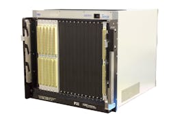
The MTS GENASYS GX7017 chassis, shown in Figure 1, is based on the 6U PXI standard and features a 16-wire analog bus. Key benefits associated with the chassis include:
- support for up to nine switching modules, offering more than 2,200 multiplexed, hybrid test connections;
- support for up to eight GX5960 digital modules, providing up to 256 digital channels;
- an integrated MAC Panel SCOUT cableless interface; and
- integrated high-level SwitchEasy switching software for end-to-end signal routing.
Courtesy of Marvin Test Solutions
In a similar way, Pickering Interfaces’ customers confirmed the need for thermocouple simulation. Pickering already had developed PCI- and PXI-based simulators for resistive and RTD sensors and strain gages, so the sensor simulation area was a familiar one. Paul Bovington, simulation product manager, discussed one customer’s use of a wide variety of thermocouples in maintenance systems. He said, “This customer builds equipment to monitor the vibration, temperature, and overall condition of equipment such as turbines and pumps for the power generation, aerospace, and gas and oil sectors.
“This equipment lets the operator/owner know if maintenance is required prior to having a catastrophic failure, which is always much costlier than stopping operations and performing necessary maintenance. In some instances, there are hundreds of thermocouples in the system.” He concluded, “When building a new system for the end customer, it is desirable and theoretically simpler to simulate these thermocouples for final test rather than connecting to the device to be monitored.”
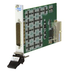
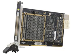
Pickering’s model 41-760 PXI millivolt thermocouple simulation module (Figure 2) is available with 32, 24, 16, or eight independently programmable channels, each capable of being set to a voltage between -100 mV and +100 mV. The total span is divided into three ranges so that the user can trade resolution for range: ±20-mV with 0.6-µV resolution, ±50-mV with 1.5-µV resolution, or ±100-mV with 3-µV resolution. Each channel has a two-pin output, and the simulated cold sides are independent of each other and chassis ground.
Courtesy of Pickering Interfaces
Further justifications
Higher speed
In addition to customer requests, other factors such as changes in communications standards and higher data rates also influence how new-project budgets are spent. According to Oliver Rovini, technical director at Spectrum Instrumentation, “The development of the [PXIe] M4x.44xx digitizer modules followed customer requests…. PXIe offers many advantages over the older PXI standard including transfer speed and a number of clock and trigger distribution and synchronization features. [Like PXI,] it also allows users to easily create test systems that may contain a variety of instrument types from a number of different suppliers.”
He continued, citing a defense customer’s airborne laser imaging, detection, and ranging system that will be based on the PXIe modular instrumentation platform. He said, “Because the system is deployed in an aircraft, it needs to be small and compact, with relatively low power and good cooling. Furthermore, the construction must be robust and rugged to avoid any problems due to mechanical vibration. PXIe addresses all of these issues.”
A Spectrum press release describes the dual-width M4x.44xx 3U modules as having 250-MHz bandwidth and “… two or four fully synchronous channels in resolutions of either 14 bits for sampling at rates up to 500 MHz or 16 bits for sampling at rates up to 130 MS/s or 250 MS/s…. Each channel has its own separate monolithic ADC and low-noise signal conditioning circuitry… [with] six gain ranges (±200 mV up to ±10 V), selectable input impedance of 50 Ω or 1 M Ω, and AC or DC coupling.”
The release also states,”… the new PXIe modules can immediately utilize the FPGA-based firmware options that already exist for the [company’s older] PCIe cards. Block averaging and block statistics packages are available for high-trigger-rate applications that require hardware-based processing functions.”
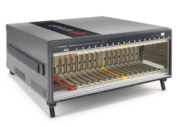
Keysight Technologies has launched the M9019A Gen 3 PXIe chassis (Figure 3) that the datasheet describes as having 16 PXIe peripheral slots with “… a maximum data bandwidth of 8 GB/s each. The two-link system slot has a maximum data bandwidth of 24 GB/s when all 24 PCIe lanes are utilized.” The datasheet continues, “When combined with the M9023A PXIe system module, the M9049A PCIe adapter, and an external PC with a Gen 3 x 16 PCIe slot, up to 16 GB/s of data bandwidth can be achieved between the PC and PXIe chassis.”
Courtesy of Keysight Technologies
The company’s Jim Armentrout, global modular sales and marketing manager, said, “This new Gen 3 chassis effectively doubles the size of the data ‘highway’ to provide faster streaming and more flexibility, both for current Gen 2 cards (think lots of digitizers) and for future Gen 3 cards. Besides bandwidth, this chassis also provides new features that improve system integration. Front-panel triggering ports allow advanced synchronization between other chassis or box instruments. In addition, a Keysight-exclusive multichassis power sequencing capability makes it simple to start up multichassis systems by removing the need to power up multiple chassis in a certain order. The new yellow card guides in the chassis timing slot help users realize that this is a timing slot where they should not try to plug in a PXI card.”
He concluded, “The new systems cards greatly improve both system flexibility and performance. In a single chassis application, they double the data bandwidth back to an external host PC. In multichassis applications, such as MIMO, they provide high-performance chassis interconnect capability as well as both star and cascade configuration options. This gives the customer the ability to trade off performance and cost.”
Speed also drove GuideTech to develop the two-channel DC to 2.7-GHz GT668PXIe continuous time-interval analyzer (CTIA) as an upgrade to the previous DC to 400-MHz
GT658PCI instrument. As the company’s CEO Ron Sigura commented, “Time and frequency customers demand continuous performance improvement as their requirements grow with Moore’s law.”
The GT668 event timer is available in PCI, PCIe, PXI, and PXIe formats. Each type of board supports averaged time resolution of 1 ps, 2 ps, 15 ps, or 40 ps at a maximum measurement rate of 4 M/s. The instrument accepts signals with frequencies up to 2.7 GHz and makes measurements relative to a 100-MHz time base phase locked to either an internal 10-MHz OCXO with ±25 ppb over a 0°C to +45°C temperature range or to an external 5-MHz or 10-MHz clock.
Measurements include time interval error, one pulse/s monitoring, jitter measurements, PLL and clock jitter, spread spectrum modulation, PLL lock time, frequency, period, pulse width, skew, and rise/fall time. Because of CTIA technology, timestamps are relative to the first event edge, which the company claims eliminates the need for supplemental triggers, pattern markers, or clock recovery circuits.
Extended capabilities
National Instruments (NI) developed the PXIe-6570 digital pattern instrument to enhance the capabilities of the previously launched Semiconductor Test System (STS). A press release reporting the announcement of the new product at the company’s NIWeek conference states, “The NI PXIe Digital Pattern Instrument … features 100-MVector-per-second pattern execution with independent source and capture engines and voltage/current parametric functions at up to 256 synchronized digital pins in a single subsystem.”
A white paper offers a more detailed description.1 Each two-slot module provides 32 channels with access to 128 Mb of data per channel. The deep vector memory allows simultaneous storage of many different patterns, which can be selected as required to speed up testing.
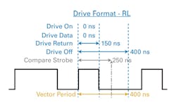
One of 31 user-defined timing sets describes how an individual channel’s vector data should be interpreted. A timing set contains the time period of the vector, a drive format for the pin—selected from nonreturn, return low, return high, and surround by complement—and placement of the digital edges. Figure 4 shows the placement of the vector’s four edges and the compare strobe.
Courtesy of National Instruments
To monitor signals input to a pin, the output drive is turned off so that the compare strobe can sample the channel’s state relative to user-set upper and lower thresholds. In addition, as the white paper explains, “… pin parametric measure units (PPMU) … source and sink voltage or current to make DC parametric measurements. The PPMU functions of the PXI digital pattern instrument are commonly used for continuity or open/short and leakage testing.”
Chris Nunn, NI’s product manager for modular instruments and test systems, clarified the timing shown in the figure. He said, “A timing set will be applied to all pins in a specific vector for a specific cycle. Therefore, even though the pin [in Figure 4] is in a drive state and isn’t using the compare strobe that was assigned for that particular timing set, another pin specified in that pattern could be in a compare state at that cycle using that compare edge. Furthermore, that pin could be driving now with that time set, but cycles later change to comparing (using the same time set), and at that point, it would be using the compare strobe location. In the figure, we are trying to illustrate all edges of a timing set, but [for] that specific cycle, that specific pin doesn’t need to look at the compare strobe. There will be many instances of this sort of thing throughout a pattern because the timing set is used for many cycles and many pins.”
Higher channel density distinguishes the PXIe-429-64 test and simulation instrument (Figure 5) from Avionics Interface Technologies (AIT), a division of Teradyne. As described by Troy Troshynski, marketing and product development manager at the company, “In a single PXI Express slot, the module provides up to 32 transmitter and 32 receiver ARINC 429 channels with concurrent operations supported on all channels. Additionally, the PXIe-429-64 provides the user with software control of the amplitude and DC offset of the output ARINC 429 signals.”
Courtesy of Avionics Interface Technologies
Troshynski explained that as well as requiring fewer chassis slots for high channel-count simulations, “The PXIe-429 … takes advantage of the higher data host system interface data rates with PCI Express … with its output voltage control, [the module] also provides the user with the ability to do complete verification of UUTs including tests that require altering the electrical characteristics (amplitude and offset) of the ARINC 429 signals.”
The ARINC 429 standard specifies a 32-bit frame that is divided into five fields. Data is transmitted at either 12.5 kb/s or 100 kb/s and uses a “… bipolar, return-to-zero format. This is a tri-state modulation consisting of HIGH, NULL, and LOW states”—as described in an AIT ARINC-429 tutorial document. The tutorial further clarified the bus operation: “In bipolar, return-to-zero, or RZ format, a HIGH (or 1) is achieved with the transmission signal going from NULL to +10 V for the first half of the bit cycle, then returning to zero or NULL. A LOW (or 0) is produced by the signal dropping from NULL to -10 V for the first half bit cycle, then returning to zero. With a return-to-zero modulation format, each bit cycle time ends with the signal level at 0 volts, … [this eliminates] the need for an external clock, creating a self-clocking signal.”2
The PXIe-429-64 module supports
- concurrent operation of all Tx/Rx channels at high data rates,
- full error injection and detection,
- rate-oriented label transmission,
- label selective trigger for capture/filtering,
- IRIG-B time code encoder/decoder for data correlation, and
- real-time recording and post analysis of multiple channels.
In contrast to modules with narrow functionality, source/measure units (SMUs) have broad applicability. NI and Keysight have introduced relatively low-power SMUs—20 W for NI’s PXIe-4135 and 18 W for Keysight’s M9111A—but both instruments have additional features that improve performance relative to earlier models.
Keysight’s Armentrout said, “… the M9111A PXIe high-speed SMU is a single-slot, two-quadrant module that delivers up to 13 V, ±1 A or up to 6 V, ±3 A, 18 W. It speeds up test with high-speed output that quickly changes voltage in 10 to 50 µs. The M9111A can change its voltage, settle that voltage, and make a measurement in <1ms which is 20x faster than our previous-generation SMUs.”
NI’s Ravichandran Raghavan, product manager—PXI platform, described the PXIe-4135 as having, “… four-quadrant operation and [sourcing] up to 20 W of DC power with voltage and current boundaries at ±200 V and ±1 A. The analog-to-digital converter technology of this module enables high-precision measurements with a current resolution of 10 fA and the power of a digital control loop to customize the SMU response to any load. Engineers can use the NI PXIe-4135 SMU to measure low-current signals and take advantage of the high-channel density, fast test throughput, and flexibility of NI PXI SMUs for applications such as wafer-level parametric test, materials research, and characterization of low-current sensors and ICs.”
The future
A number of trends are evident at different levels. For example, new communications standards that emphasize MIMO technology imply the need for test and development systems with tightly synchronized multichannel and wide bandwidth capabilities. This combination of requirements is a very good match to recently developed RF PXI/PXIe modules.
Higher up the food chain, manufacturers are addressing test applications by providing complete PXI/PXIe-based solutions. This means that the manufacturer is blurring the line between his instrument business and his customer’s application-specific test capabilities. The STS is an example of how NI has created a test system based on standard products such as LabVIEW and TestStand test executive software and PXI/PXIe chassis and power supplies. In addition, special modules such as the PXI digital pattern instrument have been developed for this application. Further, the company has invested in the capability to understand what the application really requires.
Similarly, Keysight develops and publishes reference solutions—sets of hardware and software that address a particular application in depth. One of the latest is the digital interconnect reference solution. As described by the company’s Armentrout, “This reference solution enables signal integrity characterization of multiport interconnect products. The user experiences a turnkey manufacturing cable test system with full crossbar PXI-VNA calibration of 32 ports in a single chassis and up to 26.5 GHz [bandwidth] with [a] friendly, graphical user interface. A custom API wrapper is interfaced to PLTS software to offer complete domain analysis with a production test interface. The digital interconnect reference solution supports any linear passive interconnect faster and easier, including backplanes, connectors, and PCBs.”
References
- “PXI Digital Pattern Instruments Bring Semiconductor ATE-Class Digital to the Open PXI Platform,” National Instruments, August 2016.
- ARINC 429 Protocol Tutorial, Avionics Interface Technologies, Doc.
No. 40100001.
For more information

