Members can download this article in PDF format.
Buck regulators are versatile components known for their efficiency. However, deploying them in products that must meet the electromagnetic-interference (EMI) requirements of groups such as the Comité International Spécial des Perturbations Radioélectriques (CISPR) can present challenges.
The high switching frequencies that drive the regulators’ high performance can exacerbate emissions. Fortunately, regulators with integrated capacitors, and employ spread-spectrum switching techniques, can help you meet EMI requirements with ease.
Sponsored Resources:
- How buck regulators with integrated capacitors help lower EMI and save board space
- Reducing high-frequency EMI with integrated capacitors
- Utilizing Dual-Random Spread Spectrum to improve EMI performance
Integrated Capacitors
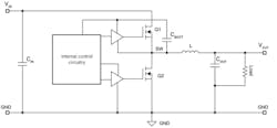
Figure 1 shows a simplified buck regulator with input capacitance (CIN) representing both low- and high-frequency capacitors. When a high-side metal-oxide semiconductor field-effect transistor (MOSFET) Q1 turns on, high transient currents (di/dt) flow in the high-frequency capacitor current loop.
1. Capacitors CIN and CBOOT experience high transient currents when the high-side MOSFET Q1 switches.
Key factors in limiting EMI are to keep the areas of such current loops experiencing high di/dt as small as possible while also minimizing the surface area of high-transient-voltage (dv/dt) nodes. To help with both of these factors, you should locate input capacitors as close as possible to the buck-regulator IC.
Layout constraints, however, often preclude optimal capacitor placement. To overcome layout limitations, you can use buck regulators such as Texas Instruments’ LMQ66430-Q1 and LMQ61460-Q1, which deliver 3 A at 36 V and 6 A at 36 V, respectively, and are both qualified to the AEC-Q100 quality standard for automotive applications.
Each buck regulator integrates high-frequency input capacitors inside the regulator package. This integration reduces the need for external capacitors and results in the smallest possible input-capacitor current-loop area, thereby minimizing parasitic inductance in the loop and reducing the amount of energy emitted.
In addition, both offer enhanced packaging to minimize switch-node ringing. The LMQ61460-Q1, for example, comes in TI’s HotRod flip-chip-on-leadframe package, which has no internal bond wires, thereby eliminating a significant source of input loop inductance.
In addition, note the boot capacitor (CBOOT) in Figure 1. Its job is to supply charge to the high-side gate driver when Q1 is on. (Internal circuitry refreshes this capacitor’s charge when Q1 is off.) CBOOT establishes another high-di/dt current loop whose area should be minimized. The TI LMQ66430-Q1 integrates this capacitor inside its package, thus limiting the area of the high-di/dt current loop and associated high-dv/dt voltage node while also reducing the need for external components.
Slew-Rate Control
One common way to minimize EMI in buck-regulator designs is to make use of slew-rate control. With the LMQ61460-Q1, for example, an external boot resistor (RBOOT) controls the strength of the high-side FET driver during turn-on. A value of 100 Ω for RBOOT results in an approximately 2.7-ns switch-node rise time, which virtually eliminates overshoot.
Although slew-rate control does reduce emissions, it’s at the expense of lower efficiency. By utilizing a buck regulator with integrated input capacitors, though, you might be able to achieve the desired EMI performance without resorting to slew-rate control, as demonstrated by the example in Figure 2.
2. The plot on the left represents a buck regulator with no integrated capacitors but using maximum slew-rate control, while the plot on the right shows a device having integrated capacitors but no slew-rate control.
The plot on the left in Figure 2 represents a buck regulator with no integrated capacitors but it uses maximum slew-rate control, while the plot on the right represents a device with integrated capacitors but has no slew-rate control. The device with integrated capacitors achieves a 4- to 5-dBmV improvement in emissions performance compared with the device with maximum slew-rate control. And the superior performance of the device with the integrated capacitors comes with no sacrifice in efficiency.
Spread-Spectrum Techniques
In addition to minimizing the areas of high-di/dt current loops and high-di/dt voltage nodes, you can take other steps to minimize EMI. A switching device like a buck regulator generates EMI at its switching frequency and at the harmonics of that frequency.
One way to mitigate such EMI is to use a spread-spectrum technique to dither the switching frequency. It can attenuate the fundamental and blend the harmonics into a smoothed averaged waveform whose values remain within limits set by the relevant EMI standards.
Common spread-spectrum implementations employ either triangular or pseudorandom modulation. Triangular modulation works well at the fundamental frequency, allowing you to reduce your EMI filter size and cost, but it’s less effective at higher frequencies. In addition, many triangular modulation schemes have a triangle-wave frequency in the 4- to 15-kHz range. That can create an audible tone if coupled into nearby audio circuitry or even a ceramic capacitor resonating at the same frequency.
Pseudorandom modulation, on the other hand, may not attenuate the fundamental as evenly, thereby limiting the size reductions possible for your filter. However, it maintains its performance at high frequencies and doesn’t exhibit the audible tone issue.
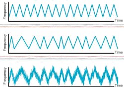
To get the benefits of both approaches while limiting the drawbacks, you can choose a switching regulator that employs TI’s proprietary Dual-Random Spread Spectrum (DRSS) technology, such as the LMQ66430-Q1. The DRSS approach begins with triangular modulation (Figure 3, top). Then, it dithers the triangle waveform’s frequency randomly (Figure 3, middle) to address the audible tone issue, spreading the tone into white noise.
3. TI’s DRSS technology begins with triangular modulation, randomly dithers the triangle frequency, and adds pseudorandom modulation on top of the dithered-triangle modulation.
Finally, to address triangle modulation’s suboptimal high-frequency performance, DRSS adds pseudorandom modulation on top of the dithered-triangle modulation (Figure 3, bottom). In addition to spreading the audible tone into white noise, DRSS goes a step further to actively reduce that noise.
Conclusion
High transient currents are major drivers of buck-regulator EMI, and minimizing the areas of high-di/dt current loops and high-dv/dt voltage nodes is critical. Integrating high-frequency capacitors inside the regulators minimizes those areas as much as possible to assist with meeting EMI compliance requirements.
Choosing a device with TI’s proprietary DRSS technology can further reduce unwanted emissions. Finally, buck regulators with integrated capacitors also help cut BOM count and reduce power-supply size.
Sponsored Resources:


