Members can download this article in PDF format.
Engineers typically push the edge of the envelope in design. However, when it comes to using traction inverters to boost EV range, they’re proving they want to burst right through the envelope.
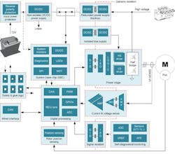
A traction inverter manages the flow of energy from the high-voltage battery pack to the motor (Fig. 1), which turns the wheels to propel the vehicle. The efficiency and performance of traction inverters directly impacts an EV’s driving range on a single charge. Thus, inverter technology is a key area of development thanks to its potential benefits to vehicle performance.
Inverter power density is a key enabler here. Indeed, the target of OEMs in the U.S. market is a lofty 100 kW/L by 2025 (the output power density of proposed lab inverters at the moment is around 80 kW/L).
The Advent of SiC
To build the next generation of these systems, design engineers must reduce power losses and improve system efficiency to make EVs more reliable, increase driving range, and enhance safety. To do so, the industry is widely adopting silicon-carbide (SiC) field-effect transistors (FETs), which are ideal for high-efficiency, high-frequency, and high-power-density applications due to their high switching capabilities. The use of SiC also enables 800-V dc bus voltages.
One of the most notable features of SiC transistors is that they allow engineers to design higher-power systems in the same footprint with weight and gain efficiency across temperature, speed, and torque. This, in turn, helps increase the vehicle’s driving range. But while SiC MOSFETs are more efficient, like any transistor, they will experience some power loss when switching.
Fortunately, selecting a SiC isolated gate driver with real-time variable gate-drive strength reduces switching losses. It also enables designers to optimize system parameters such as efficiency (which impacts EV operating range) and SiC voltage overshoot (which impacts reliability).
The architecture of a traction inverter varies with vehicle type. Plug-in hybrid electric vehicles (PHEVs) and battery electric vehicles (BEVs) have a three-phase voltage-source inverter topology, with power levels in the 100- to 500-kW range. The battery pack can either directly connect to the inverter dc input or a dc-dc boost converter can be used to step up the battery voltage and supply the inverter with a controlled dc voltage.
Higher Efficiency with Real-Time Variable Gate-Drive Strength
Because SiC MOSFET power modules are so important to a vehicle’s operation and efficiency, designers must carefully consider how to properly drive them. Driving SiC MOSFETs in an EV traction inverter, especially at high power levels and with 800-V buses, requires reliable low- to high-voltage galvanic isolation technology, high drive strength, fault monitoring, and protection against various fault conditions.
Speaking of protection, all of the usual circuitry must be there: fast overcurrent protection, short-circuit protection, isolated temperature and voltage sensing, and undervoltage lockout. The traction inverter also should include monitoring circuits to prevent system-level failure modes such as over- and under-torque, unintentional motor commutation, or motor shutdown.
The new UCC5880-Q1 reinforced isolated gate driver offers features that enable EV powertrain engineers to increase power density and reduce system design complexity and cost while achieving their safety and performance goals. This 20-A SiC gate driver certainly has its spec sheet right: Gate-drive strength varies from 5 A to 20 A, and it is variable through both a 4-MHz bidirectional Serial Peripheral Interface (SPI) bus or three digital input pins.
The UCC5880-Q1 comes with design support tools including evaluation boards, user’s guides and a functional safety manual to assist you with your designs. Preproduction quantities of the automotive-grade, ISO26262-compliant UCC5880-Q1 are available now, on TI.com, in a 10.5- × 7.5-mm, 32-pin shrink small-outline package (SSOP). Pricing starts at US$5.90 in 1,000-unit quantities.
Blueprint for a SiC-Based Traction-Inverter System
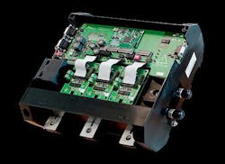
The TIDM-02014 reference design (Fig. 2) is an 800-V, 300-kW, SiC-based inverter reference design developed by TI and Wolfspeed. It provides a starting point for designers and engineers to achieve a high-performance, high-efficiency traction-inverter system and get it to market faster.
The isolated gate driver coupled with TI’s isolated bias supply solution significantly reduces the PCB size, providing more than a 2X smaller PCB area and a height of less than 4 mm. Plus, it eliminates 30+ discrete components improving system power density.
In addition, TI’s high-control performance MCUs featuring tightly integrated real-time peripherals enable effective traction motor control even at speeds greater than 20,000 RPM. A fast current-loop implementation helps minimize motor torque ripple and provides smooth speed-torque profiles.
Other nice tidbits include:
- Features of the real-time variable gate-drive strength enable improvement in system efficiency by minimizing the SiC switching power losses and accurate bias supply minimizes conductive losses.
- Isolated gate drivers and bias-supply module reduce PCB area by 30%.
Conclusion
With EV traction inverters approaching 300-kW power levels, the need for higher reliability and higher efficiency is imperative. There’s also a credible argument to be made that all of the progress mentioned here represents a page turned in TI’s book of traction-inverter advancement. Even a 2%, SiC power-stage efficiency gain is significant in that it can correspond to an additional seven miles of range per battery. For an EV user who charges their vehicle three times per week, it could mean more than 1,000 additional miles per year.


