Hall-Effect Current Sensors Promote Precision Control
Members can download this article in PDF format.
High-voltage systems including electric vehicles, industrial robots, communications infrastructure equipment, and renewable-energy installations often require accurate current measurements. You can use a current-shunt or Hall-effect sensor to make such measurements, but recent innovations have given the Hall-effect current sensor an edge up over current shunts in many applications.
Tradeoffs in Current Sensing
Consider the tradeoffs between the shunt and Hall-effect approaches to current measurement. Traditionally, shunt-based current measurement has provided better accuracy and lower drift over the entire operating-current range, over high and low temperature extremes, and throughout the useful life of the system in which it’s used.
A shunt-based scheme uses a stable amplifier to monitor and develop a signal proportional to the shunt-resistor voltage, and hence proportional to the current through the resistor. Subsequently, a precision analog-to-digital converter (ADC) digitizes the amplifier output for monitoring and processing by a host microcontroller unit (MCU).
Downsides of this approach include heat dissipation in the shunt resistor, which impacts efficiency. In addition, you must decide whether to locate the shunt on either the high side or low side of the current load.
A low-side shunt can introduce differences in the ground potential between the load ground and sensing-circuit ground, which could have implications for your overall system design. If you place the shunt on the high side, you will need an isolation amplifier or other form of isolation, and you may need a separate high-side power supply as well to power the sensing circuit. Consequently, a shunt-based approach can lead to high bill-of-materials (BOM) counts and design complexity, and the components involved can result in extended propagation delays.
Simplified Sensor Setup
In contrast, a Hall-effect sensor can provide a much simpler solution. To understand the Hall effect, envision a flat rectangular conductor—a Hall element—carrying a current through a magnetic field perpendicular to the rectangle. The Lorentz force will cause charge carriers to migrate laterally (perpendicular to both the magnetic field and the direction of current flow), inducing the Hall voltage across the element.
In a typical Hall-effect sensor, a conductor carrying the current of interest passes through a gapped toroidal core to establish the perpendicular magnetic field. A Hall element carrying a constant current and placed in the gap develops a voltage proportional to the field, and thus to the current of interest.
In addition to the Hall element, a Hall-effect current-sensor IC includes amplification to provide a usable output signal. This approach inherently provides galvanic isolation, eliminating the need for separate isolators. But, Hall-effect current sensors have traditionally exhibited significant drift over temperature and lifetime.
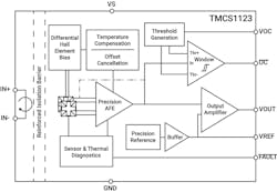
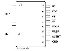
Now, however, engineers at Texas Instruments have developed a Hall-effect current sensor—the TMCS1123 —that incorporates precision signal-conditioning circuitry with built-in drift compensation to limit lifetime sensitivity drift error to ±0.5% and total sensitivity error over both lifetime and temperature to ±1.75%. It employs differential Hall-effect sensing, significantly reducing interference or crosstalk from stray external magnetic fields. Figure 1 shows the TMCS1123 block diagram, and the table defines the pin functions.
Closer Look at the Current Sensor
The TMCS1123 develops an output voltage proportional to an input current up to 75 A continuous. The five available sensitivity options include 25, 50, 75, 100, and 150 mV/A. To save cost and space, the device doesn’t require a bulky and expensive external toroidal core. Instead, its Hall element responds to the magnetic field established internally by current flowing through the leadframe of the isolated input of the small-outline IC (SOIC) package.
An internal reinforced isolation barrier and external creepage and clearance distances of at least 8.1 mm provide for a working voltage of 1,100 V DC (Fig. 2). The device operates from a single 3- or 5.5-V power supply.
The TMCS1123’s 250-kHz small-signal bandwidth and 600-ns propagation delay provide the performance necessary for the control of high-voltage AC and DC applications involving rectifiers, drivers, or other high-voltage circuit topologies. The device can measure currents in AC inputs, DC buses, and motor phases (Fig. 3).
The device supports bidirectional and unidirectional current sensing and features a fast overcurrent-detection function that responds within 500 ns. Three variants include different internal references that determine the output voltage corresponding to a 0-A input current. A version with a 2.5-V reference supports bidirectional current sensing using a 5-V supply, a version with a 1.65-V reference supports bidirectional current sensing using a 3.3-V supply, and a version with a 0.33-V reference supports unidirectional current sensing using either a 3.3- or 5-V supply.
Evaluation Module
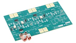
Factors to consider during Hall-effect current-sensor designs include accuracy as well as current and voltage levels. To help you explore an optimal Hall-effect design for your current-measurement requirements, TI offers The TMCS1123EVM evaluation module (Fig. 4). The EVM includes five separate sections so that you can experiment with each of the five sensitivity levels.
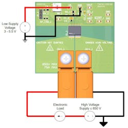
Figure 5 shows a test setup enabling low-side current measurements for one EVM section incorporating a TMCS1123A1 version with 25-mV/A sensitivity. The other sections are identical except for the TMCS1123 version numbers. Three versions of the complete EVM are available—one for each zero-current reference voltage.
Conclusion
Hall-effect sensors are emerging as the preferred devices for accurate, stable current measurements in high-voltage systems. TI’s TMCS1123 offers a 75-A continuous current rating and 1,100-V working voltage while limiting sensitivity error over lifetime and temperature to ±1.75%. To help you get started integrating Hall-effect current sensors into your designs, the company’s TMCS1123 evaluation modules let you experiment with a range of sensitivity options.


