Design Balanced Op-Amp Circuits For Performance And Simplicity
In a balanced op-amp circuit, the op-amp inputs see equal impedances looking into the circuit. Balanced circuits provide better performance by cancelling some input errors and have a simple RF/RI gain formula that works for all cases, where RF is the feedback resistor that connects from the output to the inverting input and RI is the input resistor that connects the input voltage source to an op-amp input.
It’s simple enough. The gain is positive if RI connects to the non-inverting input and negative if RI connects to the inverting input.
Related Articles
- An Enhanced Op-Amp Balanced Amplifier
- What's The Difference Between Operational Amplifiers And Instrumentation Amplifiers?
- Efficiently Design An Op-Amp Summer Circuit
To design a balanced circuit, select RF (such as 100 kΩ), and calculate RI for each input by dividing RF by the magnitude of the gain. If the gain is positive, connect RI to the non-inverting input. If it’s negative, connect it to the inverting input. Finally, add a balance resistor to create equal impedances for the op-amp inputs. The balance resistor connects from the op-amp input with the higher impedance to ground.
Alternatively, you can use Daisy’s Theorem to get the balance resistor, which states that the sum of the gains in a linear circuit must be equal to +1. The balance resistor adds a ground input to the circuit. Select the ground input gain to satisfy Daisy’s Theorem and you have a balanced circuit.
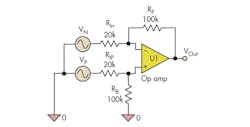
Consider a differential op-amp circuit that has a positive input with gain of +5 and a negative input with gain of –5 (Fig. 1). RF was selected to be 100 kΩ. The input resistors are 100 kΩ/5 = 20 kΩ. You can get the balance resistor by noting that the inverting input sees RF (100 kΩ) and RIn (20 kΩ) while the non-inverting input has RIP (20 kΩ). It needs a 100-kΩ balance resistor. Alternatively, the signal gains add to zero and need a +1 ground gain to satisfy Daisy’s Theorem.
The procedure works for all combinations of positive and negative inputs. If you have been using the 1 + RF/RI formula, you may have some misconceptions that should be cleared up.
For negative gains, the –RF/RI formula is the same as the classical op-amp formula. For a positive gain, the RF/RI gain formula differs from the 1+ RF/RI formula, which only applies to the non-inverting amplifier circuit and only for an input connected to the non-inverting op-amp input. The RF/RI formula applies for all positive inputs in a balanced circuit.
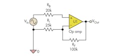
A look at a non-inverting amplifier circuit clarifies the source of the confusion (Fig. 2). To show that both formulas create the same result, we need to add a balance resistor. The standard circuit has the input connected directly to the non-inverting op-amp input.
To protect the op amp and provide a way to balance the circuit, a balance resistor RB has been added. If you select RB = RF in parallel with RI, you will have a balanced circuit, and RB does not affect the circuit gain. Since the non-inverting input impedance is infinite, no current flows through RB, and the non-inverting op-amp input voltage is VIn.
The RF and RI labels come from the standard circuit. Note that RI is not a signal input resistor. It is the ground input resistor. The VIn input resistor is missing in the standard circuit. It has been added above and labeled RB.
You can analyze the circuit in many ways. With the 1 + RF/RI formula, the gain is 1 + 100 kΩ/25 kΩ = 5. With the balanced circuit formula, the gain is RF/RB = 100 kΩ/20 kΩ = 5. With Daisy’s Theorem, the ground gain is –RF/RI = –4 and the input gain needs to be +5 to have the gains add to 1.
The results are the same. The confusion is created by the labeling. It comes from how the equations are derived. Classical analysis derives the non-inverting formula using circuit assumptions. If the op-amp gain is large, both op-amp inputs must have the same voltage to create a finite output voltage. This assumption makes the analysis of the circuit simple.
In summary, the 1 + RF/RI formula works only for the non-inverting circuit. The RF/RI formula works for all positive inputs in a balanced circuit. There is no conflict. The balanced circuit formula is derived from Plato’s Gain Formula:
VOut/VIn = p × ZF/ZI
K9 Analysis represents a circuit component as an impedance Z, where Z can be an ideal component, a two-terminal network for a non ideal component, or a resistor. Plato’s Gain Formula is the unified gain formula for a single op-amp circuit. The gain is a constant p times the feedback impedance (ZF) divided by the input impedance ZI.
For a circuit with equal impedance at the positive (+) and negative (–) op-amp inputs, the gain magnitude is simply ZF/ZI, or RF/RI for resistors. The gain is positive for inputs connected to the positive op-amp input and negative for inputs connected to negative input.
Constant p is equal to –1 for negative gains and ZP+/ZP– for positive gains. ZPn is K9 notation for the parallel combination of the impedances that connect to node n. ZP+ is the parallel combination of the positive input impedances that connect to the non-inverting op amp input.
Since the inputs are ideal sources, this is the impedance seen by the non-inverting op-amp input. ZP– is the parallel impedance of the negative input resistors and the feedback impedance ZF. The ZP terms will vary with the circuit and depend on the number of circuit inputs. For a balanced circuit, the ZP terms cancel and the magnitude of the gain is ZF/ZI.
Plato’s Gain Formula is derived via K9 Analysis using nodal analysis. If you’re still skeptical, compare Plato’s Gain Formula to the gain formula in a textbook solution. They should match. If the positive input is connected to ground, add an input resistor to avoid singularities. (This may require a bit of algebra.)
The intent of K9 Analysis is to make analog circuit design simple. With the balanced-design technique, op-amp circuit design becomes simple, and you are no longer constrained to existing op-amp circuits.
If you are using multiple op amps to implement a linear circuit with a single output, you may be able to reduce the circuit to a circuit with a single op amp. Just get the circuit gains and design a balanced, single op-amp circuit. Keep in mind that one op amp can implement any linear circuit equation.
No longer is a single op-amp design with multiple positive and negative gains difficult. You do have to create a balanced design by adding a balance resistor, which determines the ground gain. Since ground is zero voltage, you may think that the ground input does not contribute to the op-amp output. That’s wrong! Ground is never zero voltage. There is always a little ground noise. Reducing the ground gain will reduce the output noise.
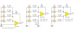
Let’s look at a four-input audio mixer, where we want each input to have a gain of 2 (Fig. 3). Since this is audio, the sign of the gain may not matter, and a gain of +2 or –2 is acceptable. Set RF = 100 kΩ, and each input resistor will have a value of RF divided by two, or 50 kΩ. The circuit on the left is an inverting-amplifier mixer circuit. The middle one is a balanced mixer with two positive and two negative inputs. The circuit on the right has the V1 and V2 input gains changed to +2.5.
What’s the ground gain in the inverting mixer circuit? The inputs add to a gain of –8. Daisy’s Theorem has the ground gain at +9. Since all the gains are negative, the circuit does not need a balance resistor. The non-inverting op amp input can be connected to ground.
If you can afford an extra resistor, you can create the balanced design. Two of the inputs are moved from the inverting input to the non-inverting input. What’s the ground gain now? The input gains add to zero and the ground gain is +1. This is a big noise reduction.
You can even do better by making the sum of the signal gains equal to 1, in the third variation, where two of the input gains are +2.5 and the other two are –2, so the gains add to +1. The ground gain is 0 and no balance resistor is needed. This circuit adds no ground noise to the output, which is nice.
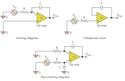
So far we have shown how to reduce your circuit and eliminate ground noise by using a balanced design. K9 Analysis uses impedances. If we use a capacitor for ZF, we can build an integrator circuit. Figure 4 shows the textbook integrator circuit on the left. The integrator has a negative gain, but can we design an integrator with positive gain?
In the circuit in the middle, the input has been moved to the non-inverting input. This circuit is not balanced, as the inverting input sees the feedback capacitor, while the non-inverting input sees the input resistor.
To balance the circuit, we need to add a resistor equal to the input resistor to the inverting op-amp input and a capacitor equal to the feedback capacitor to the non-inverting input. Thus, both inputs see equal impedances and are balanced.
The balance components were connected to ground. However, you can connect them to a voltage-source input to create a different circuit, such as a differential integrator, by returning the inverting input-balance resistor to a second input, or an ac amplifier by returning the balance capacitor to an input. These circuit techniques allow you to convert inverting textbook circuits to non-inverting circuits, as long as you maintain balance.
But there are caveats. The simplified positive-gain formula hides the fact that positive gains are very interactive. Changing any input impedance can change all the positive gains. You need to have a balanced circuit for the simple positive formula to apply. Most changes require a change in the balance impedance. In contrast, negative gains are independent and don’t interact. If all the signal gains are negative, you do not need a balanced circuit.
Also, op-amp circuit voltages are limited. You need to verify that inputs do not cause the output to saturate. For positive inputs, you also need to verify that the inputs do not violate the common-mode input range. Note that if all the signal gains are negative, the op-amp inputs are at ground potential and the common-mode input range is not an issue. You also need to verify that the circuit is stable. The design equations are solutions of circuit equations. Although the solutions are correct, there is no guaranty that the circuit will remain in the solution state.
Summary
Balanced op-amp designs are relatively easy. Keep in mind that op amps prefer balanced design, so consider a balanced op-amp design for your next linear circuit.
Plato’s Gain Formula is ZF/ZI for balanced circuits. Just pick a feedback impedance and select the input impedances for the desired gains. Connect the input impedance to the non-inverting op-amp input for a positive gain or the negative op-amp input for a negative gain. Create a balanced circuit by adding balance impedances.
For amplifier designs, use Daisy’s Theorem to find the ground gain. If the circuits requirements allow, explore changing the gain signs to reduce the ground gain and consider implementing the circuit with a single op amp.
Dieter Knollman is a retired member of the technical staff at Bell Labs. He has a PhD from New York University and about a dozen patents. He created K9 Analysis to simplify analog analysis (Lucent has given permission to share the K9 analysis) and taught circuit design at a state university in the 1980s.
About the Author
Dieter Knollman
Technical Staff, retired
Dieter Knollman is a retired member of the technical staff at Bell Labs. He has a PhD from New York University and about a dozen patents. He created K9 Analysis to simplify analog analysis (Lucent has given permission to share k9 Analysis) and taught circuit design at a state university in the 1980s.


