Circuits of Chaos: Building Lorenz, Chua, and Rossler Strange Attractors
Members can download this article in PDF format.
What you’ll learn:
- Chaotic circuits can arise from either computed (using Analog Computers or Digital Computers) solutions to coupled differential equations or from unstable systems/circuits.
- A new open-source circuit board, featuring Chua, Lorenz and Rossler Strange Attractors, as well as unstable circuits, is now available for everyone to make.
- What the outputs of each chaotic circuit look like on the test bench.
Editor note: I had indicated that a circuit board with Strange Attractors was under its designer’s evaluation at the time we published our Analog Computing blog on the Lorenz Attractor. I’m pleased that Sariel has completed his evaluation, the board is fully functional, and he’s given our readers this exclusive first look into the operation of a circuit board he graciously open-sourced. This means any of you, including schools, can have a little fun and make any or all four of its attractor circuits. All that’s needed is a power supply and an oscilloscope with X-Y capability, as was mentioned in the Analog Computing blog.—AndyT
To most people, "chaos" means confusion or randomness, but in mathematics, "mathematical chaos" refers to a deterministic behavior governed by precise nonlinear equations. A system is chaotic when it shows extreme sensitivity to initial conditions. In chaotic systems, the state doesn’t settle into a fixed point or predictable oscillation, but continuously evolves in a manner that’s highly sensitive to initial conditions and is hard to predict.
Designing and simulating electronic circuits that display chaotic behavior isn’t difficult. Chaos can be observed in virtually all aspects of life, including biology, geology, chemistry, finance, psychology, medicine, all branches of engineering and physics, economics, and countless other areas.
Chaotic electronic circuits demonstrate the important aspects of chaos theory and are easy to implement. Some of these circuits can be used as analogs for other chaotic systems from different fields, sharing similar mathematics and thus making it easier to study them without modifying the real system.
Chaotic circuits divide into two types: pure chaotic circuits, and analog-computing circuits for chaotic systems. The first type consists of electronic circuits that are unstable, have some positive feedback, and show negative resistance. These circuits oscillate periodically but can also become chaotic, with output voltages changing in a highly unpredictable manner.
The second type includes electronic circuits that act as analog computers or smaller analog-computing blocks. These circuits, composed of summers, integrators, dividers, multipliers, and inverters, solve nonlinear differential equations in real-time. The solutions to these equations represent the output of a chaotic circuit.
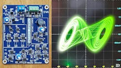
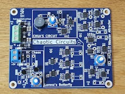
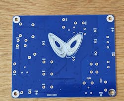
To demonstrate chaos and gain hands-on experience, a circuit board was designed with four chaotic circuits (Figs. 1 and 2). Two of them represent unstable circuits, while the other two are analog-computing blocks that solve a set of nonlinear differential equations. All of the circuits shown in this article can be easily simulated in any SPICE program (such as LTSpice) with the same parts and values shown in the successive circuits.
Circuit #1: Chua’s Circuit
This circuit was developed by Leon Chua (in 1983), whose notoriety is based on being the first to postulate the existence of the memristor. His 1971 paper identified a theoretical symmetry between the nonlinear resistor (voltage vs. current), nonlinear capacitor (voltage vs. charge), and nonlinear inductor (magnetic flux linkage vs. current).
As a professor, his area of specialization was in nonlinear circuits. Chua was the first to design an electronic circuit that showed chaotic phenomena. Until then, there were only computational approaches that solved a nonlinear set of equations exhibiting chaotic behavior.
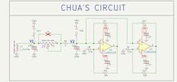
Chua’s original circuit utilized a superficial nonlinear negative resistor (for sustained oscillations). Over the years, many researchers have invented numerous ways for practical implementation of the negative resistor. Figure 3 shows the implementation of Chua’s circuit.
When Chua's circuit is analyzed using Kirchhoff's circuit laws, a set of three nonlinear ordinary differential equations is obtained. Depending on the values of the capacitors, inductor, and series resistor, this system can become chaotic.
In the lab, the variable resistor (R4) was tuned until the circuit entered a chaotic working point, which was found to be around 1,500 Ω. The same result was obtained in simulations.
To observe the chaos in this circuit, the nodes V2 and V1 (as shown in the schematic) are plotted in X-Y mode, with V1 versus V2, respectively. By varying the resistance of R4, the circuit can be set to sustained oscillation (a circle in the phase plane) or a steady state (a singular point in the phase diagram). Once R4 reaches about 1,500 Ω, the circuit operates in chaos, and a Strange Attractor (“Chua’s Attractor”) in the shape of a double scroll appears on the screen (Fig. 4).
Circuit #2: Simple RC Chaotic Oscillator
Chua's circuit requires an inductor and several active components to create a nonlinear negative resistor. However, chaos can be achieved with even simpler circuits.
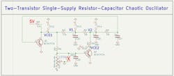
A few years ago, a fictitious author named Kajnjaps published a simple circuit on several websites. This circuit, which requires no operational amplifiers or inductors, demonstrates chaos with just two transistors. Kajnjaps is a pseudonym for one of the authors of the IEEE paper titled “ Simple Two-Transistor Single-Supply Resistor-Capacitor Chaotic Oscillator.”
The circuit uses a lowering potentiometer (R25) to determine its behavior (Fig. 5). When R25 is high, the biasing to the lower part of the circuit (Q2) is cut off. This part has no influence over the upper part, which behaves as a normal RC oscillator that oscillates steadily depending on the RC values of the feedback network.
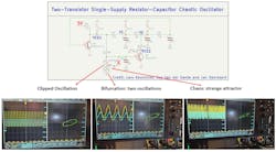
As R25 is lowered, Q2 starts to conduct and interfere with the RC oscillation, causing bifurcation (two oscillation frequencies). When R25 is lowered even further, chaos emerges. This behavior is demonstrated in Figure 6. In the circuit, the attractor can be observed in the phase plane (X-Y) by plotting V1 against the VCE1 voltages.
Circuit #3: Lorenz Butterfly Simulation Through Analog Computing
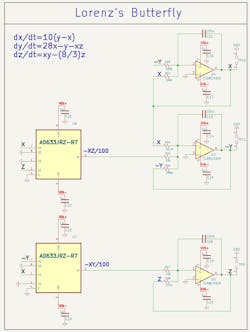
This circuit (Fig. 7) is not actually chaotic, as it lacks a negative resistor necessary to create chaotic behavior. Instead, this is a small Analog Computer block that solves the three Lorenz equations upon power-up of the circuit. This circuit is based on the work of Paul Horowitz, author of The Art of Electronics. The amplifiers and multipliers were substituted with more readily available off-the-shelf components.
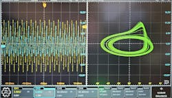
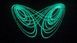
This analog-computing circuit solves these equations in real-time. The phase plane of the Z output versus X output displays the Lorenz Attractor, also known as the Butterfly Attractor, one of the most renowned strange attractors.
On the test bench, the circuit on the PCB takes time for chaos to form. Eventually, the system collapses into a steady state because the circuit includes an integrator as part of the solution to the differential equations. As with any integrator, it eventually saturates and requires a reset.
The implemented circuit doesn't have a periodic reset, so the equations are solved for a brief time until the integrators saturate. At times, even when powered, chaos isn’t observed, since it depends greatly on the initial conditions of the circuit, and even random noise, which can cause the circuit to enter or avoid chaos.
Circuit #4: Rossler Attractor
The Rossler Attractor, discovered by Otto Rossler in 1976, comprises a set of three nonlinear differential equations known for their chaotic behavior. Despite its simplicity, this attractor's trajectory forms a complex, beautiful, twisted spiral when visualized (in the XYZ plane).
The Rossler attractor can be modeled using a simple Analog Computer circuit (Fig. 8) that solves the equations’ set in real-time. (Notice how two variables were combined to show the attractor in 2D view instead of 3D). These equations are able to model chaotic chemical reactions, demonstrating how chemistry can exhibit chaos. This circuit was designed by Glen Kleinschmidt.
Figure 9 shows the attractor’s oscilloscope screen.
Conclusion
This work has shown how easy and fun it is to build chaotic circuits (Ed. note: Fig. 10 below seems to indicate that Microsoft thinks it might be a bit too much fun). Chaos can be deliberately created by solving nonlinear differential equations using analog circuits or by creating special negative resistors, though even simple transistor circuits can become chaotic.
Circuit designers might be designing a nonlinear analog circuit (like a PLL or amplifier) and, without noticing, encounter chaotic behavior in simulations or in the lab.
The circuit schematic and layout, Gerber files, BOM, and assembly position files are available on GitHub, with a courtesy zip copy of those files attached below.
Chaos Circuits PCB ZIP Archive
These files can be sent directly to any PCB manufacturer to produce a Chaotic Circuits board and is well-suited for school lab exercises. All of the components are inexpensive and easy to obtain and solder, so the board can be hand-assembled or these circuits could be created on a breadboard according to the schematic. However, breadboarding does create functioning risks for chaotic circuits due to the substrate parasitics.
About the Author

Sariel Hodisan
Analog Circuit Engineer, Applied Materials
Sariel Hodisan holds a B.Sc. degree in Electrical Engineering and an MSEE degree in Systems Engineering from the Technion – Israel Institute of Technology. From 2009 to 2016, he worked as a hardware and RF engineer at leading defense organizations. Since 2016, he has been an analog circuit engineer at Applied Materials. Sariel is currently pursuing his M.Sc. degree in Electronic Engineering from the Technion, with his thesis research focusing on the use of memristors and new emerging devices for analog, high-speed, and RF circuits.
