Modeling on Mondays: An Intro to Simulation of Vacuum-Tube Triodes in SPICE (Part 2)
What you’ll learn:
- Linear, small-signal AC models can be useful in the analysis and design of vacuum-tube-based circuits.
- Under large-signal conditions, nonlinear models are typically required.
Introducing the Triode
Almost 120 years ago, electronics began in earnest with the invention of the triode vacuum tube (VT). On January 29, 1907, Lee de Forest filed his first application for patent of the Grid Audion, and the patent (U.S. Patent No. 879,532) was granted on February 18, 1908.1 The Audion was presented as a RF detector having increased sensitivity over the Fleming valve, as well as over the two-element Audions patented earlier by de Forest.
This new device incorporated a third element, a so-called control grid, placed between the anode and the cathode (the plate and the filament/cathode) within an envelope that had been (poorly) evacuated. This three-element device―referred to as a triode, for obvious reasons―showed an ability to amplify (weakly) the signal appearing at its input.
The essence of operation is straightforward. The device is thermionic. Its filament acts as a cathode, boiling off electrons when heated. A metal plate—the anode—when held at a positive potential with respect to the cathode, collects electrons freed from the cathode. Those two elements form the basis of a diode rectifier.
Now, though, position a third element between the cathode and the plate. If that element―the control grid―is such that most of the electrons originating from the cathode can make it through to the plate if the plate-to-cathode voltage vPK is held positive, then not much has changed from diode operation. That is, until a negative potential is placed on the grid with respect to the cathode.
If the grid-to-cathode voltage vG1K is negative, some of the electrons otherwise being accelerated to the plate will be driven back toward the cathode. The more negative vG1K is, the fewer the electrons are that make it to the plate. Thus, we now have a voltage-controlled current source. And the control grid’s current is minuscule. (Note that if vG1K becomes positive, the grid itself draws electrons. It effectively becomes another anode, grid current flows, and care must be taken to keep that delicate element from destruction.)
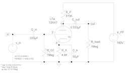
The triode is the simplest of VTs capable of amplification. A typical schematic symbol for a triode is that of U1a in Figure 1. Pin 1 is the plate (P), pin 2 is the control grid (G1), and pin 3 is the cathode (K).
The particular VT in the circuit is a type 12AX7, which has two triodes contained within a single envelope. The cathode in each triode is indirectly heated; i.e., there’s a separate, electrically isolated, element―the heater―that heats the cathode so it will boil off electrons. The heater isn’t involved as an active element in the signal path in most (not all) VTs, and it’s usually not shown as part of the VT’s symbol in a schematic. Rather, the heaters of all VTs in a circuit are gathered off to the side of the schematic, shown in the vicinity of, and with connections to, a dedicated heater power circuit.
Some VTs have directly heated cathodes, just as with de Forest’s Audion. For those cases, the cathode and the heating element are one and the same. The heating element is called the filament, and the filament is included in the schematic symbol since it’s also the cathode.
The triode’s symbol is meant to be reminiscent of its construction, but the construction is only very rarely planar. Instead, there’s a very roughly cylindrical nature, with the cathode being a cylinder surrounding the heater, the control grid circling the cathode, and the plate then surrounding the grid.
The RCA Receiving Tube Manual (the latest volume published, RC-30,2 is readily available as a reprint) has, in addition to data on receiving tubes, excellent introductions to the construction and operation of VTs, as well as several examples of VT-based circuits. References 3 through 6 are classics that provide more-technical looks at the construction and operation of VTs. Also, Tyne7 provides a thorough and fascinating history of the evolution of the VT through 1930.
Using SPICE to Model VT-Based Circuits
SPICE is a very popular circuit analysis and simulation program available in the public domain. LTspice is a freeware implementation of SPICE that incorporates schematic capture and a waveform viewer.
Techniques for analysis and synthesis of VT-based circuits are, of course, well established, and those techniques were extended to semiconductor-based circuits. Only the device models changed―and, for the basic models, not by much. The linear, lumped-parameter, small-signal models for VTs, FETs, and BJTs appear strikingly similar. A recent Electronic Design article on modeling common active electronic devices8 provides an overview and useful linear, small-signal models, one of which―the gm equivalent circuit―targets triode VTs.
If a circuit is assumed to be such that the VT remains in its active region of operation, then we can insert the gm equivalent circuit (i.e., model) for the VT in place of the VT’s symbol, and we can carry out, by hand, an AC analysis of the circuit. (Normally, we should first determine the quiescent operating point, or Q-point, for the VT if we want to use appropriate values for its ac parameters: amplification factor μ, transconductance (or mutual conductance) gm, and dynamic plate resistance rp. (Pick any two, since μ = gm rp.)
In fact, this isn’t a bad place to start. A good rule to follow is to never simulate anything―circuit or otherwise―unless you understand roughly what that thing is supposed to be doing! And then, make sure you understand what your simulator is doing, what models are being used, and roughly how those models act.
Getting Started with the Simulation
Let’s get started. The circuit in Figure 1 will be our example, with (half of) a 12AX7 as our active device of choice. Get a copy of a datasheet for the 12AX7 (see, e.g., Reference 9). General Electric datasheets typically provide ample information and helpful complements of graphs.
The circuit is a common-cathode gain stage having resistor values and supply-voltage values matching those of the sixth version down the chart for the “Class A Resistance-Coupled Amplifier” depicted in the GE datasheet. The only exception is the value of the grid resistor R_G1 (Rg1 in the datasheet), which has been chosen to be 1 MΩ, the typical upper limit stated by manufacturers for triodes. Note that the topology―the “circuit shape”―of this basic common-cathode VT gain stage is identical to that of a basic common-source gain stage based on an FET, and the analysis procedure is similar. Only the component values and supply voltages are different.
The values of the inter-electrode capacitances appearing in the gm equivalent circuit are available in the GE datasheet, but the values in all VT models discussed herein are adjusted to include reasonably expected stray capacitance associated with wiring at the VT’s socket. Specifically, the values used are as follows: Cg1k = 3.0 pF; Cg1p = 1.4 pF; and Cpk = 1.9 pF.
If you decide to analyze the gain stage under quiescent (i.e., dc or bias) conditions, you’ll find, with the use of the graph entitled “Average Plate Characteristics” on the 12AX7’s datasheet, that IPQ ≈ 0.21 mA, VPKQ ≈ 72 V, and VG1K ≈ ‒1 V.
Now go ahead and replicate, using LTspice, the circuit in Figure 1, replacing the symbol for the 12AX7 with the gm equivalent circuit. The datasheet gives gm as 1,600 μmhos (1,600 μS) and rp as 62,500 Ω for a Q-point given as VPKQ = 250 V and IPQ = 1.2 mA. Use those values of gm and rp blindly to start with, realizing, from the plot of the plate characteristics, that the values of μ, gm, and rp vary with the particular Q-point selected. (From the plot, gm ≈ 900 μS and rp ≈ 100K at the Q-point of the circuit as drawn.)
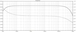
If you run an AC sweep, you should get a frequency-response plot―gain and phase-shift curves―that matches the set of curves in Figure 2. A sinusoid of amplitude 0.2 V was used as the input when generating the curves.
Now, for the purpose of entertainment (and insight), change the amplitude of the sinusoid to be, say, 10 V. Nothing changes in the frequency-response plots, although a quick glance at the 12AX7’s plate curves makes clear that the output waveform should be distorted significantly if the sinewave has an amplitude greater than about 1 V. But our model is a linear, AC model. None of the circuit’s DC operation―the power-supply voltage VPP, the Q-point, etc.―has any say in the simulation’s results.
Forging Ahead Gets Symbolic
At this point, you might want to construct your symbol for a triode VT in LTspice. Define a .SUBCKT that describes the gm equivalent circuit being employed and replace, in your LTspice schematic, the circuitry of the gm model with the VT symbol.
Formation of symbols and subcircuits is described in various LTspice resources and tutorials available online. The symbols and subcircuits folders are found as subfolders \sym and \sub in LTspice’s folder. (And if you’re not interested in creating your own triode symbol, be aware that one is already made up in LTspice; look in the [Misc.] elements.)
In the next part of this series, we’ll look at two models that address the nonlinear nature of the triode.
References
1. Lee de Forest, 1908, “Space Telegraphy,” U.S. Patent No. 879,532. Filed Jan. 29, 1907, and issued Feb. 18, 1908.
2. RCA Receiving Tube Manual RC-30. Reprinted by Antique Electronic Supply, Tempe, Az., www.tubesandmore.com.
3. Truman S. Gray, Applied Electronics, 2nd ed. (Wiley, New York, 1954), 881 pages.
4. Jacob Millman, Vacuum-tube and Semiconductor Electronics (McGraw-Hill, New York, 1958), 644 pages.
5. Karl R. Spangenberg, Vacuum Tubes (McGraw-Hill, New York, 1948), 860 pages.
6. E. Leon Chaffee, Theory of Thermionic Vacuum Tubes (McGraw-Hill, New York, 1933), 652 pages.
7. Gerald F. J. Tyne, Saga of the Vacuum Tube (Howard W. Sams, Indianapolis, 1977), 494 pages. ISBN: 0-672-21470-9.
8. Stephen A. Dyer, “Modeling on Mondays: SPICE Modeling of Common Active Devices—An Overview (Part 1),” Electronic Design.
9. GE Electronics, “12AX7-A Twin Triode” (datasheet ET-T3030 dated 12-61).
