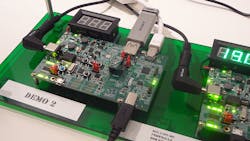
There is a lot more to the USB 3.1 Type-C discussion than its reversible nature (see “USB 3.1 Type C Connector Is Reversible” on Electronic Design). Power management is a key differentiator as is the ability to handle more than one interface through alternate mode operation. This will allow a single connector on a device like a laptop, smartphone, or tablet to link to different devices other than USB devices such a DisplayPort monitor.
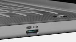
From a user’s perspective, usage can be simple but confusing. For example, there is no need to worry about the cable because the same connector is at both ends and, of course, it is reversible so plugging it in is easy. The problem is, what does it really do? For example, a single connector can support multiple functions, but what are they? The use of tiny logos (Fig. 1) is one way to indicate what is supported. In this case, it is USB and DisplayPort. In the latter case, the device at the other end has to support DisplayPort on a Type-C connection.
Power management is actually a more complex issue since either end of a connection can source power and that can change over the time of connection. For example, a monitor plugged into a hub may receive power from a laptop that is also plugged into the hub. This might change if the hub could be powered directly and it is then plugged in. The amount of power that can be exchanged will depend on a number of variables including the cable.
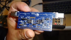
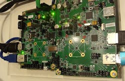
Type-C cables are intelligent and incorporate their own microcontroller to handle negotiations. That is great once the cable is working and the chip is hidden behind a connector, but developers will want a little more access. In this case, a reference design like the one from Cypress Semiconductor (Fig. 2) comes into play. This is essentially a Type-C cable, but the headers provide developers with access to control signals.
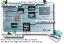
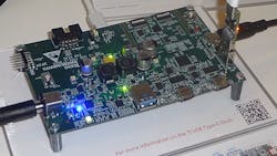
From a developer’s perspective, the complexity of the system grows as alternate modes are added to the mix. Pericom’s chipset highlights the various components in the mix, including the crossbar switch to link the host’s interfaces with the Type-C connection (Fig. 3). Re-drivers are needed because of the speeds involved.
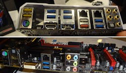
The Type-C connector is already showing up in motherboards like SuperMicro’s C7Z170-SQ and Gigabyte’s GA-Z170X-Gaming5 (Fig. 4). These motherboards use Intel’s Z170 chipset that supports latest Skylake processors, including overclocking options for the process, memory, and GPU. Of course, USB 3.1 is part of the mix.
A new feature in USB 3 land is authentication support. NXP’s reference design board (Fig. 5) has a header that allows a security module to be added. This allows authentication of services on the board. This could be access to a device or providing a non-standard power source. The authentication support is a standard option and a number of vendors were showing similar platforms at the Intel Developers Forum show.
Lattice Semiconductor is known for its flash FPGA devices. They have recently moved into the USB space (Fig. 6). The initial set of support chips uses a conventional SoC design approach but future chips will employ their FPGA technology, providing developers with a more hardware programmable platform.
Power modes defined by the USB Implementers Forum specify different power options, allowing a device to power devices that tend to be more power-hungry.
Texas Instruments’ power-delivery reference design (Fig. 7) supports 5 V and 20 V solutions. It is based on TI’s TPS65982 chip. It can deliver up to 60 W (3 A at 20 V). It can work with multiplexors if alternate mode is needed.
USB 3.1 Type-C support is definitely changing the way USB connections work. There is added complexity for both the developer and consumer.
About the Author
William G. Wong
Senior Content Director - Electronic Design and Microwaves & RF
I am Editor of Electronic Design focusing on embedded, software, and systems. As Senior Content Director, I also manage Microwaves & RF and I work with a great team of editors to provide engineers, programmers, developers and technical managers with interesting and useful articles and videos on a regular basis. Check out our free newsletters to see the latest content.
You can send press releases for new products for possible coverage on the website. I am also interested in receiving contributed articles for publishing on our website. Use our template and send to me along with a signed release form.
Check out my blog, AltEmbedded on Electronic Design, as well as his latest articles on this site that are listed below.
You can visit my social media via these links:
- AltEmbedded on Electronic Design
- Bill Wong on Facebook
- @AltEmbedded on Twitter
- Bill Wong on LinkedIn
I earned a Bachelor of Electrical Engineering at the Georgia Institute of Technology and a Masters in Computer Science from Rutgers University. I still do a bit of programming using everything from C and C++ to Rust and Ada/SPARK. I do a bit of PHP programming for Drupal websites. I have posted a few Drupal modules.
I still get a hand on software and electronic hardware. Some of this can be found on our Kit Close-Up video series. You can also see me on many of our TechXchange Talk videos. I am interested in a range of projects from robotics to artificial intelligence.
