Reduce MCU Power in IoT Apps with These Techniques
This file type includes high-resolution graphics and schematics when applicable.
Microcontrollers are the bedrock of the Internet of Things (IoT) movement. They interface with the plethora of sensors that provide information to the cloud and other IoT devices via wired and wireless links. Though they may be small and use little power, a significant amount of power is consumed when taken collectively. They’re often battery-powered or even scrounge power from other sources, such as solar power. Thus, it becomes paramount to minimize power utilization in order to reduce the overall load and increase operational time for battery-operated IoT devices.
There are a variety of ways to reduce power requirements for IoT devices, from architectural solutions to system transistor design to software methodologies. All can play a part, although determining the proper combination for a particular application can be a daunting task for a developer, especially when cost, functionality, security, and other factors come into play.
Low Power by Partitioning
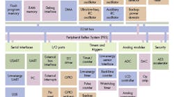
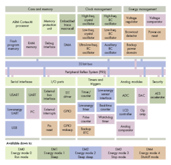
One way to conserve power is to minimize the power required to run peripherals. A number of vendors provide low-power peripherals that usually have more limited performance or functionality, but are sufficient for a wide range of applications Silicon Labs takes that approach (Fig. 1)—its low-energy peripherals can also run when the system is in deep-sleep (EM2) mode with the CPU core off. The typical peripherals will operate in the higher-performance sleep (EM1) mode, though this uses more power.
The challenge for developers is to determine if transitions between modes can occur fast enough to handle associated events. By having active peripherals, information is able to be collected and possibly analyzed to determine if a transition needs to occur. This transition typically wakes up the processor to programmatically handle the event.
Silicon Labs' Peripheral Reflex provides an intermediate functionality to link peripheral events so that an event from one peripheral can trigger another peripheral. For example, an analog-comparator transition would cause an analog-to-digital converter (ADC) to capture some information, and it might cause a counter to increment all without waking up the processor.
Most microcontroller vendors have a form of the Peripheral Reflex system implemented on certain products. Cypress Semiconductor's PSoC (see “Smart Peripherals Make Low-Power IoT Possible”) takes this to the extreme with almost FPGA-like configurability. PSoC chips have a set of analog and digital building blocks with a programmable connection matrix. Peripherals like UARTs and timers can be customized and linked for autonomous operation offloading the processor.
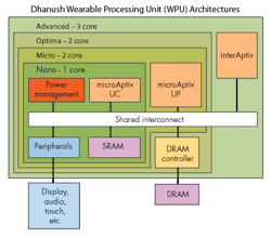
Sometimes a processor is needed to handle a job, but a high-performance core may be overkill for particular functions. Ineda Systems takes a hierarchical approach to the problem with two or more cores (Fig. 2). It allows a higher-performance core to handle jobs that aren’t possible with the lower-performance core, while allowing the latter to handle jobs such as peripheral management (see “Hierarchical Processors Target Wearable Tech”).
Asymmetric core designs are much more common even at the low end of the spectrum. NXP's LPC4300 includes ARM Cortex-M4 and Cortex-M0 cores (see “Dual-Core Cortex-M4 And M0 MCU Redefines Digital Signal Control”). The lower-end processor is often the manager that handles watchdog chores in addition to low-speed, low-power peripherals.
Low-Power Transistor Design
Another way to conserve power is to implement a low-power transistor design. Shrinking the system can help, but often this approach is more about improving performance. Of course, getting the job done faster and subsequently sleeping can result in a low-power solution as well.
Ambiq's subthreshhold Apollo Cortex-M4 design optimizes transistor design to reduce overall power requirements (see “Subthreshold Cortex-M4F Design Sips Less Power Than Cortex-M3”). The resulting system draws less power, making it possible to use high-performance features like floating point. The chip consumes only 30 µA/MHz executing from flash, and a mere 100 nA in ultra-low-power sleep mode with the real-time clock (RTC) running.
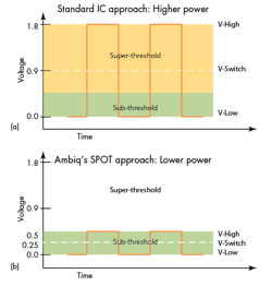
The power savings reaped from Ambiq's approach are due to the difference between conventional super-threshold and sub-threshold designs (Fig. 3). Keith Odland, Senior Director of Marketing at Ambiq Micro, explains the differences between sub- and super-threshold:
“At the very elemental level, sub-threshold and super-threshold really refer to the ‘state’ of a field effect transistor (FET) as it ‘turns-on.’ In other words, when a transistor is completely on (large gate to source voltage; VGS), it conducts much more current than when the transistor is ‘kind-of-on’ or ‘just starting to turn on’ where it conducts much less current. This difference can be several orders of magnitude (i.e. 1000s of times different).”
The problem is quite difficult, and Ambiq's part actually operates the many of the digital circuits in a “near-threshold” region. Still, the resulting system delivers an EEMBC ULPBench (see “Interview: Markus Levy Discusses The EEMBC Ultra Low Power Benchmark”) benchmark result of 377. The previous watermark was 185.
Sometimes memory can make a difference in a low-power design. Texas Instruments’ FRAM-based MSP430 addresses applications where non-volatile storage allows fast start up and shut down while allowing complete RAM retention (see “Microcontroller Utilizes FRAM For Code And Data”). Flash-based solutions cannot retain RAM when the system is completely shut down, and moving data between flash and RAM is slow and uses more power.
Low-Power Software Design
Embedded developers usually take advantage of low-power modes to minimize power requirements. This was once a simple chore due to the limited number of power modes. Typically, lower-power modes limited system functionality in a simple fashion, such as reducing the clock rate or limiting the number of active peripherals.
These days, more power-mode options are available, with many more complex variations. The added lower-power peripherals discussed earlier often operate differently for each power mode. Managing power modes in a multitasking system becomes even more difficult as devices and applications have different requirements at different times.
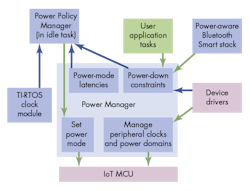
Texas Instruments’ TI-RTOS addresses this challenge (see “RTOS Employs Profile-Based Power Management” on electronicdesign.com). The TI-RTOS power-management system (Fig. 4) utilizes constraint and status information from applications and device drivers to determine when a state transition should occur and the proper state for the device. This allows a Bluetooth Smart stack to indicate the need to be periodically enabled, in order to exchange information with wireless peers. The stack doesn’t specify if a transition occurs, but lets the RTOS know when events take place (e.g., completion of an operation). The TI-RTOS is available in ROM for many of the company’s microcontrollers, such as the CC2640 SimpleLink Bluetooth chip.
