Measure Projectile Velocity Optically With An Ohmmeter
Article updated 10/04/22
Stephen Woodward, University of North Carolina, Marine Sciences, Venable Hall, CB3300, Chapel Hill, NC 27599
Archery and target shooting with firearms and air guns are just a few of the many sports and pastimes that involve high-speed projectiles. A handy accessory for any of these activities is some means of accurately measuring the speed of the projectile (e.g., air gun pellet muzzle velocity). This enables the condition of the gun, bow, etc., to be monitored, allowing optimum performance and accuracy to be maintained.
Commonly called chronographs, such devices are commercially offered at reasonable prices (less than $100). For some folks, though, the do-it-yourself approach maintains its perennial appeal. For this group, the circuit shown is offered as a cheap, simple, and functional alternative.
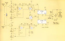
Like most electronic chronographs, this one works via optical detection of the passage of the projectile over two points separated by a known distance, D (in this case, the five inches separating phototransistors Q1 and Q2). The time-of-flight, T, between the detectors is, of course, inversely proportional to the average speed, S, of the projectile: S = D/T.
Optical detection of a projectile whizzing past a given point is not always trivial—especially for BBs and other small-caliber air gun pellets that may fill only a small fraction (about 1%) of the detector's field of view. The logarithmic optical-detection method employed here is borrowed from an earlier IFD ("Available-Light Phototachometer Simplifies Outdoor Remote Sensing," Electronic Design, January 25, 1999) and has a wide dynamic range compatible with low-contrast signals in both outdoor and indoor lighting.
Velocity measurement begins with the passage of the projectile over Q1. The resulting partial occlusion of Q1's view generates a negative pulse at A1's noninverting input of about 500 µV for every 1% of light blocked. A1 and A4 boost and invert by 70 dB to produce a reset (start) pulse to the free-running 14-bit ripple counter U3. Following the projectile's passage, U3 resumes counting from zero, tallying the time of flight (T) with 250-ns resolution.
The same process occurs when the projectile reaches Q2, generating a reset (stop) pulse to U2, marking the end of the flight between detectors. This action results in the capture of a phase difference between the 244-Hz (4 MHz/16,384) square-wave outputs of free-running U3 and U2 equal to T. This phase difference will persist until detection of a subsequent TOF event. Therefore, until then, the TOF measurement remains available for readout.
The problems then remaining are: (1) conversion of this time measurement into the desired reciprocal velocity measurement, a process usually accomplished with software division via a microcontroller, and (2) provision for display of the calculated velocity. This is where that ohmmeter comes into play.
Enhancement-mode MOSFET Q7 (RON < 0.25 Ω) is arranged so that it only turns on when U3's output is at logic zero and U2's output is simultaneously at logic one. This state occurs once every 4096-µs U2/U3 cycle and has a duration exactly equal to the phase difference, T. So, the duty factor of Q7's conduction is equal to T/(4096 µs). As a result, the average conductance of the Q7/RCAL combination is equal to T/(4096 µs × RCAL).
This makes the average resistance seen by an ohmmeter connected to the output terminals equal to ROUT = (4096 µs)RCAL/T. Because T = D/S, D = 5 in. = 0.417 ft., and RCAL = 102 Ω, we have: ROUT = 4096 µs × 102 × S/0.417 = 1 Ω/ft/s. Thus, the ROUT resistance readout is a direct linear representation of projectile velocity expressed in ft/s. Depending on the 244-Hz ripple-rejection characteristics of the ohmmeter, ripple-filter capacitor C1 may not be necessary.
Although the circuit constants and flight-path dimensions shown are optimized for the measurement of gun-muzzle velocities in the range of 204 to 3500 ft/s, other component choices can easily adapt the ohmmeter/chronometer to other scenarios and preferences. For example, changing RCAL to 310 Ω will change the scale factor to 10 Ω = 1 m/s; RCAL = 69.8 Ω yields 1 Ω = 1 mph.
This article appeared in Electronic Design Oct. 28, 2001.
About the Author
W. Stephen Woodward
Steve Woodward has authored over 50 analog-centric circuit designs. A self-proclaimed "certified, card-carrying analog dinosaur," he is a freelance consultant on instrumentation, sensors, and metrology freelance to organizations such as Agilent Technologies, the Jet Propulsion Laboratory, the Woods Hole Oceanographic Institute, Catalyst Semiconductor, Oak Crest Science Institute, and several international universities. With seven patents to his credit, he has written more than 200 professional articles, and has also served as a member of technical staff at the University of North Carolina. He holds a BS (with honors) in engineering from Caltech, Pasadena, Calif., and an MS in computer science from the University of North Carolina, Chapel Hill.

