IBIS Modeling (Part 2): How to Create Your Own IBIS Model (Download)
Simulation plays a key role in building any system. It allows designers to foresee problems and prevent time-consuming and costly revisions. The goal is always to do it right the first time! In the case of simulating high-speed digital interfaces, a simple PCB trace could affect the quality of the signal if not designed properly. In signal-integrity simulations, an IBIS (input/output buffer information specification) model is used as a representation of the device’s digital interfaces.
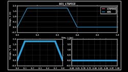
As discussed in Part 1 of this article series, IBIS is a behavioral model that describes the electrical characteristics of the digital interfaces of a device through tabulated current vs. voltage (I-V) and voltage vs. time (V-T) data. It’s important for the IBIS model to be as accurate as possible and not have any parsing errors to avoid any issues when using it later.
