Modeling on Mondays: The GAP/R K2-W Vacuum-Tube Op Amp in SPICE (Part 4)
What you’ll learn:
- The availability of hierarchical blocks for describing subcircuits in SPICE can make for straightforward modeling, especially with LTspice’s schematic-capture feature.
- Neon discharge tubes can be modeled simplistically.
- The active components, two 12AX7 vacuum tubes, are popular in the audiophile and musical instrument community.
Introduction
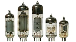
Vacuum tubes: They’ve been with us since the early 1900s. They initiated the field of electronics. The advancement of analog computing depended on them, as did the development of practical digital computers. And they’re still not dead. A variety of special-purpose vacuum tubes (VTs) are still in use out of necessity―in communication satellites, in medicine, in high-power and high-voltage applications, to name a few.
“Ordinary” VTs are still in production, too, principally in Eastern Europe and China. They remain favorites among a subset of audio enthusiasts, and among musicians who use musical-instrument amplifiers. Relatively recently, they’ve found their way back into many university classrooms and teaching laboratories as exemplars and foci around which courses, both introductory and advanced, in analog electronics have been reinvented.
VTs make great pedagogical tools for instilling “forever knowledge” associated with circuit theory and electronics; and the need to work with high voltages, at non-trivial currents, and in the vicinity of thermodynamically hot components (e.g., the VTs themselves!) provide for lessons in, and subsequent attention to, benchtop safety. Besides, EE students and others―the curious ones―seem wildly attracted to the faint, orange glow.
The seeming resurgence of interest lately in analog computing, along with the enthusiasm of some toward connection with examples from electronics past, prompts the use of an early op amp as the exemplar in developing an initial SPICE model of a VT-based circuit.
Philbrick K2-W: Where It All Began
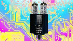
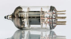
Introduced in 1952 by George A. Philbrick Researches Inc. (GAP/R) at a cost of US$22, the Philbrick K2-W became the first commercial operational amplifier. A search will turn up multiple versions of the data bulletin for the GAP/R Model K2-W Operational Amplifier, with minor variations existing.1,2 The K2-W’s design was based around a pair of high-μ 12AX7 dual-triode VTs which themselves were further hand-selected on the basis of having values of their voltage-amplification factor μ in the upper tail of the distribution of μ.
At first glance, the circuit topology appears straightforward. Three gain stages are involved:
- An input stage comprising a differential amplifier in the form of a long-tailed pair.
- A second, single-ended voltage-gain stage in a common-cathode configuration.
- A final, cathode-follower stage, which provides a significant current gain at a voltage gain of slightly less than unity.
But there are several interesting aspects and subtleties in the design―e.g., the use of positive feedback to increase the op amp’s open-loop gain; the inclusion of a Miller capacitor, placed alternatively so that the cathode follower is enclosed in the feedback path, which improves the slew rate; and the use of neon lamps as voltage regulators (Zener diodes had just recently been invented, and weren’t commercially available in 1952), to name a few. (However, concentration on these aspects, as well as discussion of second-order effects, such as the [undesirable] voltage coefficient of resistance of the Allen-Bradley carbon-composition resistors used, are outside the scope of our modeling effort herein.)
Archival information associated with the K2-W, other Philbrick op amps, and various aspects of GAP/R can be found at Reference 3. Additional notes of interest on the K2-W are contained in References 4-6.
Now let’s proceed with setting up the SPICE model.
Setting Up the Model
In Part 3 of this series, covering the simulation of vacuum tubes in SPICE,7 we outlined the construction of a model for a VT triode―quite conveniently, the 12AX7. With the symbol(s) and .SUBCKT description for the 12AX7 model in hand, it’s straightforward to proceed to the next step―that of building a usable model for an entire K2-W.
While it’s safe to say that most models in SPICE are compact, and behavioral, in nature, the circuit for the K2-W is relatively simple and comprises components that have SPICE models, since we now have a model set up for the 12AX7 triodes. Thus, our approach might best be to implement the schematic for the K2-W as a hierarchical block and create a symbol to represent that block in higher-level schematics.
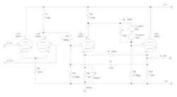
Figure 1 shows the LTspice schematic created to represent the K2-W. The model used for the 12AX7 triodes is that described in Reference 7. Although there are SPICE models for neon lamps (two NE-2 lamps were used in the K2-W), two 62-V independent voltage sources (v_neon1 and v_neon2) are used in the schematic instead. The neon lamps “fire” and act as voltage regulators (think: Zener), and simulations run faster with the independent voltage sources.
The values of a few of the resistors vary from those found in the K2-W schematics in References 1 and 2. Those values are not, within reason, critical, and they were chosen to match the values in a K2-W specimen at hand. Finally, note that the schematic has been redrawn slightly from what appears in the data bulletins, merely to make more evident the signal flow in the final stage (U2b). For each stage, the input is at the left, and the output is at the right.
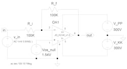
Once a symbol for the K2-W has been created in LTspice, stored in the symbol library, and associated with the block subcircuit of Figure 1, it can be used in place of the K2-W schematic in higher-level schematics. Figure 2 shows the LTspice schematic of an inverting amplifier having gain G = ‒1, with the symbol denoted by OA1 representing the K2-W.
Try it out! (Click here to download the LTspice files.)
Figure 3 depicts the frequency response of the amplifier in Figure 2. Although GAP/R gave no published information regarding the frequency response of the K2-W in this configuration, the Heath Company did publish the frequency-response curves for its EUW-19A operational amplifier, which was an almost-direct copy of the K2-W.8
The curves for the EUW-19A are similar to those in Figure 3 for the K2-W op amp, indicating that our model is giving reasonable results in this setting.
What’s Next?
Armed with a decent model (with symbol) for a 12AX7, a prospective model (with symbol) for the complete K2-W op amp, and a list of GAP/R’s published specifications, we can prepare to perform an initial evaluation of the model, relying on simulation only. Getting reasonable agreement between the manufacturer’s specifications and the “measurements” obtained by simulation would give confirmation that the prospective model will be useful.
The manufacturer’s list of electrical specifications is short. From that list, we’ll look at the following in our upcoming evaluation: input-offset voltage, open-loop gain, output impedance, output voltage range, step response, power requirements, input impedance, input current, and output current.
References
1. “Model K2-W Operational Amplifier” (data bulletin).
2. “Model K2-W Operational Amplifier” (data bulletin).
3. “The Philbrick Archive.”
4. Robert A. Pease, “What’s All This K2-W Stuff Anyhow?,” Electronic Design, Jan. 5, 2003.
5. Robert A. Pease, “What’s All This K2-W Stuff Anyhow? (Part 2),” Electronic Design, Feb. 2, 2003..
6. Andy Turudic. Nonlinearities (blog), Electronic Design, 20 May 2024.
7. Stephen A. Dyer, “Simulation of Vacuum-Tube Triodes in SPICE: Nonlinear Models,” Electronic Design.
8. “Heathkit Manual and Schematic Archive,” EUW-19A.pdf.
AndyT's Nonlinearities blog arrives the first and third Monday of every month. To make sure you don't miss the latest edition, new articles, or breaking news coverage, please subscribe to our Electronic Design Today newsletter.
